Impressiom Technique for Complete Dentures
المرحلة الرابعةصناعة الأسنان
Impression of complete denture
Its a negative registration of the entire denture bearing, stabilizing and border seal areas present in the edentulous mouth.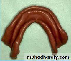
Objectives of Complete Denture Impression
Preservation of supporting tissuesRetention
Stability
Support
Esthetics
Impression Techniques
CLOUSE MOUTH or PRESSURE IMPRESSION TECHNIQUE: records impression in a condition that assumes under masticatory load.
NON PRESSURE or MUCOSTATIC IMPRESSION TEHNIQUE: records impression of the tissue in an anatomical form without pressure.
SELECTIVE COMPRESSION IMPRESSION TECHNIQUE: records impression with more compression on the tissue in certain selected areas than on other areas.
Pressure or Closed Mouth Impression Technique
This technique believes that occlusal loading during impression will record the tissue in a functional form as during swallowing and eating.Advocates of this technique believe that the periphery of dentures must be established during function.
Pressure or Closed Impression Technique
Procedure:Construct custom trays with compound occlusion rims.
Adjust oclussion rims for interocclusal distance and uniform contact in centric and eccentric position.
Load the impression material into both the custom trays simultaneously.
Have the patient close the mouth with the custom tray in mouth and moves the jaw through functional movements to record the impresssion.
Pressure or Closed Mouth Impression Technique
Disadvantages:The total time during 24 hours associated with directs functional occlusal force application to periodontal tissue is 17.5 minutes. Thus dentures are in function for ashort period of time each day.
Dentures will fit well during mastication and will lift up at rest due to tissue rebound. This result in premature contacts.
Due to constant pressure on the tissue, mucosal tissue reaction and resorption may result.
Non Pressure or Mucostatic Impression Technique
Advocates of this technique believe that impression must be recorded in an anatomical form of the tissue (resting form).
Dentures constructed by mucostatic lmpression technique have shorter flanges.
short flanges are used to prevent the denture moving in lateral direction and NOT FOR BORDER SEAL.
Metal bases which are dimensionally stable are used.
Non Pressure or Mucostatic Impression Technique
Disadvantages:Dentures do not cover broad areas.
Inadequate support.Short flanges do not support the lips and cheecks.
Selective Pressure impression technique
It combines pressure and minimum pressure principles in making impression for maxilla and mandible:Primary stress bearing areas are recorded under pressure.
Secondary stress bearing areas are recorded with minimal pressure.Peripheral areas are recorded under compression to develop seal.
The pressure can be selectively applied to the tissue by the custom trays for making final impression.
Anatomy of Edentulous Maxilla
Labial and buccal frenum and sulcus
Ridge, Cuspid eminence, Malar bone
Incisive papillaMidpalatine suture
Fovia palatinusHamular notch
Pteregmandibular raphe or ligament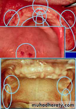
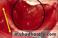
Anatomy of Edentulous Maxilla
Primary stress bearing areas::::::: horizontal portion of hard palate (1).
Secondary stress bearing areas::
::::: ridge crest (2).
Non stress bearing areas::
:::: ridge slopes (n/c).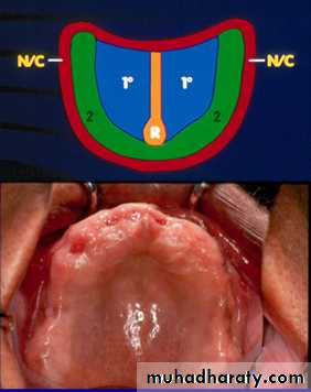
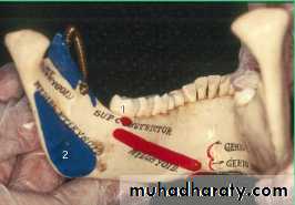
Anatomy of Edentulous Mandible
Labial, Buccal & lingual frenumLabial, Buccal & Lingual sulcus
Buccal shelfMasseter groove
Retromolar pad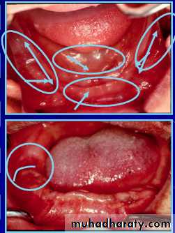
Anatomy of Edentulous Mandible
Primary stress bearing area;
::: buccal shelf
Secondary stress bearing area;
::: residual ridgeNon stress bearing area;
::: Labial & lingual inclines (n/c)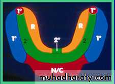
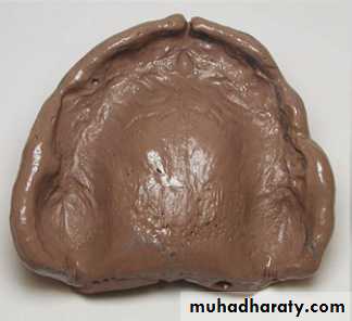
Preliminary Impression of Maxillary Arch
Select edentulous perforated stock metal tray 6mm larger than the outside surface of the ridge.Examine the extension of tray flange at labial and buccal areas.
Examine the posterior extension of the tray by dropping the handle down. It must cover the hamular notches and vibrating line.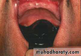
Preliminary Impression of Maxillary Edentulous Arch
Load the tray with alginate impression materialPlace small amount of impression material in the rugea area of the hard palate
Place the tray in the mouth. Hold the impression tray in the middle of the palate until the material sets.impression in modeling plastic impression compound material
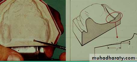
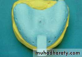
Construction of Maxillary Custom Tray
Draw the outline of wax spacer in pencil on the diagnostic cast.Do not cover the post palatal seal area with wax spacer (arrow).
Provide tissue stops at the molar and incisal regions.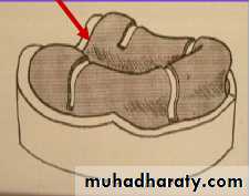
Advantages of not Covering the Post Palatal Seal Area with Wax Spacer
Completed custom tray will contact the post palatal seal area.Additional stress can be placed at this area during impression making.
Border MoldingThe shaping of the border areas of an impression tray by functional or manual manipulation of the tissue adjacent to the borders to duplicate the contour and size of the vestibule.
Adjusting Maxillary Custom Tray
Reduce the flanges of the tray 2 mm short from the sulcusAdjust labial frenal attachment
Adjust buccal frenal attachmentDo not remove the wax spacer until final impression is made
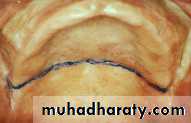
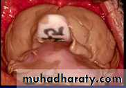
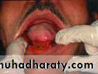
Establishing Vibrating Line
Place " T " on the crest ridge, move posteriorly until it dips into hamular notch. Join the hamular notches with pencil across the fovia palatinae. Confirm the vibrating line by asking the patient to say series of short ' AH ' sounds.the junction between the movable and immovable soft palate through the foveae palatinae is called vibrating line
Posterior Border of Maxillary Custom Tray
The posterior border of the custom tray must cover the hamular notches and extended approximately (2 mm) posterior to the vibrating line across the palate.
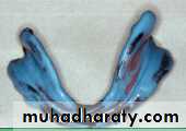
Border Molding
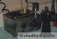
Soften the modeling plastic impression compound over the alcohol torch flame and place it over the border of the tray.After tempering in water bath at 70 F, border mold it in the mouth.
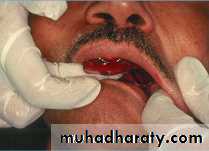
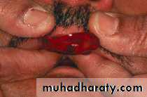
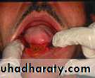
Border Molding Labial Sulcus
In the region of labial sulcus, the upper lip is elevated and extended out and then pulled downward and inward.Re-soften the compound and repeat this procedure to establish proper border molding.
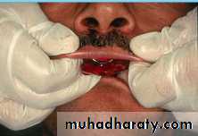
Border Molding Buccal Sulcus
In the region of buccal frenum, the cheek is elevated and then pulled outward, downward and inward.Move the cheek backward and forward to simulate movement of buccal frenum as in function during eating and smiling

Border Molding Buccal Sulcus at Tuberosity
The posterior buccal flange at the tuberosity region is border molded when the cheek is extended outward, downward and inward.with the tray in place, have the patient open mouth widely and move the jaw laterally to establish the width of the sulcus.

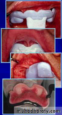
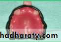
Border Molding the Post Palatal Seal Area
Place strip of softened compound at the posterior border of the custom tray and seat it firmly in the mouth.Mark vibrating line and post palatal seal area with indelible pencil.
Seat the tray again firmly in the mouth for the indelible pencil mark to be transferred to the tray. Remove excess of modeling compound.


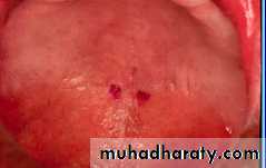
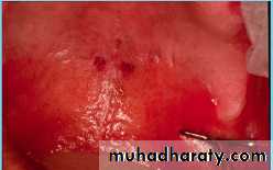
Relief for Impression
Place holes in the palate of the custom tray with no. 6 round bur to provide escape ways for the final impression material.The holes provide relief while making final impression at mid palatine raphe and hard palatal regions.
Practice Positioning Border Molded Tray in Mouth before Making Final Impression
Place the tray in mouth with labial frenum in the labial notch.Place index fingers at first molar region and seat the tray until the posterior border of the tray fits into hamular notches and across the palate.
Hold the tray in position with fingers placed in the palatal region.
Making Final Impression
The mixed impression material is placed on the tray with borders coverd.
Seat the tray in the mouth and border mold in the posterior region first and then in the anterior region.
Do not load the tray with excess of material.


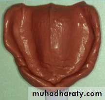
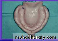
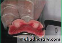
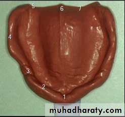
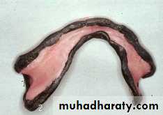
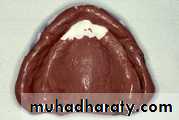
Final Rubber Base Impression with Outline Landmarks
1. Labial frenum2. Labial flange
3. Buccal frenum
4. Buccal flange
5. Pteromandibular raphe
6. Fovea palatinae
7. Vibrating line
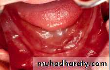
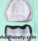
Preliminary Mandiblular Impression
Select perforated lower metal tray with (6mm) larger than the outside surface of labial and lingual ridge.Raise the handle and examine extension of tray flanges at labial, buccal, lingual and retromolar pad. It should cover all these areas.
Adapt strips of utility wax on the borders of the metal tray.
Load the tray with mixed alginate material. Place the tray in the mouth with the tongue raised slightly.

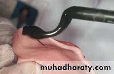
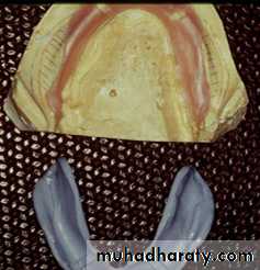
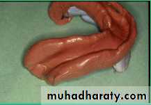
Preliminary Mandibular Impression with Modeling Plastic
Soften the modeling plastic impression compound in a water bath.The mandibular impression.
Soften the impression borders using alcohol torch, temper it in water path.
Reintroduce it in the mouth and activate the tissue to refine the impression.


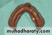
Construction of Mandibular Custom Tray
Draw the outline for wax spacer in pencil on the diagnostic cast.Do not cover the buccal shelf areas with wax.
Make additional tissue stops at the anterior regions.
Advantages
Completed custom tray will contact the buccal shelf areas.additional stress can be placed at these areas during the final impression.
The part of the tray in contact with buccal shelf areas act as tissue stops.


Adjusting Mandibular Custom Tray
Reduce the flanges of custom tray (2mm) short of the tissue reflection of the;labial, buccal, lingual sulcui and frenal attachments.
Do not remove the wax spacer until final impression is made.
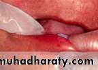
Border Molding Mandibular Labial Flange
Start border molding beginning with labial flange(1), buccal flanges (2), and finally lingual flanges (3).In the region of labial sulcus, the lower lip is lifted outward, upward and inward.
Border Molding the Labial and Buccal Flange of Lower Tray
... Anatomical Considerations
The mandibular labial frenum contains a band of fibrous connective tissue that is attached to orbicularis oris. Therefore, the labial frenum is active.


Border Molding the Buccal Flange of Lower Tray
The buccal flange must not extend lateral to external oblique ridge.The distobuccal flange must record the masseter groove and the superior border of retromolar pad.
In the region of buccal frenum, the cheek is lifted outward, upward inward, backward and forward to simulate the movement of buccal frenum.
Record masseter groove by instructing the patient to exert closing force and the dentist exerting a downward pressure on the tray.


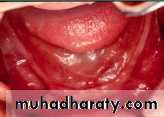
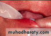
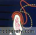
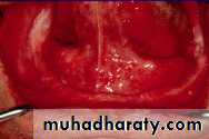
Border Molding the Lingual Flange
The lingual flange is border molded in 5 steps:Step 1. The extention of anterior lingual flange of the tray is limuted by the lingual frenum and sublingual folds, and is 2mm short of the tissues.
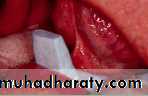
Step 2. Place the softened modeling compound on the border of the tray extending between premylohyoid fossa.
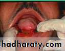
instruct the patient to protrude the tongue to establish the length of the sulcus.
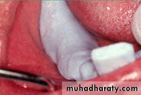
Establish Length and Thickness the Lingual Flange
Step 2. Instruct the patient to protrude the tongue to establish the length of the sulcus.the compound is re-softened and placed again in the mouth and the patient is instructed to push the tongue forcefully against the palate to determine the thickness of the flange.
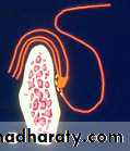
Border Molding the Lingual Flange
A. The lingual flange is extended to the most superior level of the floor of the mouth.B. Slight pressure on mucosa overlying lingual slope ensures a broader seal when tongue is at rest.
Border Molding the Lingual Flange
Step 3. Modeling compound is added to the lingual borders from premylohyoid fossae posteriorly on both sides. After placing the tray in the mouth, instruct the patient to protrude the tongue. This procedure establishes the length of the sulcus.Step 4. Repeat step 3 and have the patient move the tongue laterally and touch the corners of the mouth.
Remove the wax spacer from the tray.
Border Molding the Lingual Flange
Step 5. Add modeling compound on the distal end of the lingual flange of the tray.Place the tray in the mouth and have the patient protrude the tongue to activate the superior constrictor of the pharynx muscles (1) that support the retromylohyoid curtain and pterygomandibular raphe.
Instruct the patient to forcefully close the mouth. The resulting contraction of the medial pterygoid muscles(2) limits the retromylohyoid area.
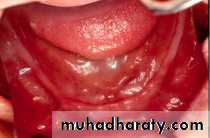
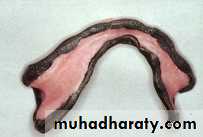
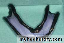
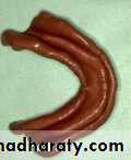
Final Rubber Base Impression
Place the tray with impression material in patients mouth.Manipulate lips and cheeks.
Have the patient move the tongue and cheek it in protruded position untill the impression sets.
Defects in Impression
Incorrect tray position in mouth resulting in underextended impression.Pressure.
Voids.
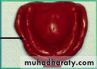
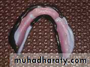
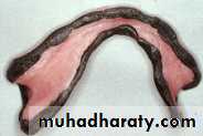
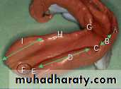
Final Impression with Border Outline Landmarks
A, labial frenumB, labial flange
C, buccal frenum
D, buccal flange
E, masseter groove
F,retromolar pad
G, lingual frenum
H, premylohyoid eminence
Scoring the Master Cast at the Posterior Palatal Seal
Step 1. With the sharp knife vertically score the cast to a depth 1.5mm along the vibrating line.Step 2. Score the anterior border of the posterior palatal seal area to adepth of 1mm.
Step 3. From step 1 bevel the cast posteriorly to step 1 to adepth 1.5mm.