

UNIVERSITY OF MOSUL
COLLEGE OF DENTISTRYBy :Dr Ali Moayid
2020-2021
Department of
Conservative Dentistry
5th YEARs
InterpretationOf Endodontic Radiograph
UNIVERSITY OF MOSUL
COLLEGE OF DENTISTRY2020-2021
Imaging and imaging interpretation are essential to the contemporary practice of endodontics for diagnosis, therapeutics, and outcome assessment.
the clinician must have knowledge of the normal imaging appearance of anatomy and morphology of maxillofacial structures such as teeth, jaws, articulation, and sinuses, as well as of common pathologic conditions affecting these structures.
UNIVERSITY OF MOSUL
COLLEGE OF DENTISTRY2020-2021
Commonly used imaging modalities used in endodontic
practice have included intraoral dental radiographs,
panoramic radiography, and more recently cone-beam computed tomography (CBCT).
One of the most important advantages of any of the aforementioned imaging techniques is that it provides the clinician with visualization of hard tissue anatomy, or pathology, not normally visible by clinical examination alone.
UNIVERSITY OF MOSUL
COLLEGE OF DENTISTRY2020-2021
Limitations of Radiographs
A radiograph is a two-dimensional shadow. They are suggestive only and are not the singular final evidence in judging a clinical problem. There must be correlation with other subjective and objective findings. The greatest fault with the radiograph relates to its physical state .
As with any shadow, these dimensions are easily distorted through improper technique, anatomic limitations, or processing errors. In addition, the buccal–lingual dimension is absent on a single film and is frequently overlooked, although techniques are available to define the third dimension.
Various states of pulpal pathosis are indistinguishable in an X-ray shadow.


UNIVERSITY OF MOSUL
COLLEGE OF DENTISTRY
2020-2021
Sometimes a teeth may become symptomatic but show no radiographic changes; thus, the lack of radiolucency should not be interpreted as an absence of a bone resorbing process.
Neither healthy nor necrotic pulps cast an unusual image.
Furthermore, periapical soft tissue lesions cannot be accurately diagnosed by radiographs; they require histologic verification. Chronic inflammatory tissue cannot, for example, be differentiated from healed, fibrous, “scar” tissue, nor can a differential diagnosis of periapical radiolucencies
In fact, investigators have demonstrated that lesions of the medullary bone often go undetected unless there is marked resorption or until the resorption has eroded a portion of the cortical plate
UNIVERSITY OF MOSUL
COLLEGE OF DENTISTRY2020-2021
There was more disagreement than agreement among the different examiners.
Importantly, the radiograph is only an adjunctive tool
and can be misleading.Information obtained from proper interpretation of the radiograph is not always absolute and must be always integrated with information gathered from a detailed medical and dental history, clinical examination, and pulp testing procedures.
UNIVERSITY OF MOSUL
COLLEGE OF DENTISTRY2020-2021
Vertical Angulation
Ordinarily, it is preferable to align the cone so the beam strikes the film at a right angle. This alignment ensures a fairly accurate vertical image. Elongation of an image, however, may be corrected by increasing the vertical angle of the central ray. Conversely, foreshortening is corrected by decreasing the vertical angle of the central ray.
UNIVERSITY OF MOSUL
COLLEGE OF DENTISTRY
2020-2021
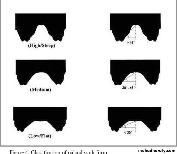
Frequently, an impinging palatal vault prevents parallel alignment of the film and the teeth. However, if the film angle is no greater than 20° in relation to the long axis of the teeth, and the beam is directed at a right angle to the film, no distortion occurs, although there is a less effective orientation of structures.
UNIVERSITY OF MOSUL
COLLEGE OF DENTISTRY2020-2021
Horizontal Angulation
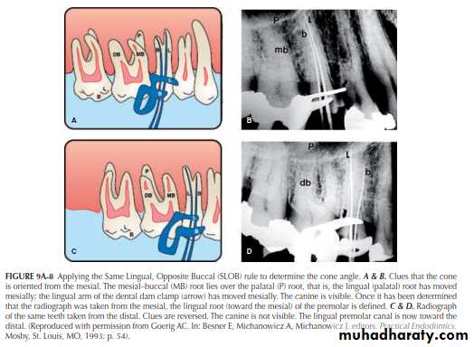
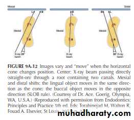
Walton introduced an important refinement method in dental radiography. By this method overlying canals may be separated, and by applying Clark’s rule, the separate canals may then be identified. Clark’s rule states that “the most distant object from the cone (lingual/palatal) moves toward the direction of the cone.”
Stated in another way, using a helpful mnemonic, Clark’s rule has been referred to as the Same Lingual, Opposite Buccal (SLOB) rule: the object that moves in the Same direction as the cone is located toward the Lingual. The object that moves in the Opposite direction from the cone is located toward the Buccal. The SLOB rule, simply stated, is “The lingual object follows the tube head.”
Ingle’s rule is MBD : If “shot” from the Mesial, the Buccal root will be to the Distal
UNIVERSITY OF MOSUL
COLLEGE OF DENTISTRY2020-2021
UNIVERSITY OF MOSUL
COLLEGE OF DENTISTRY2020-2021
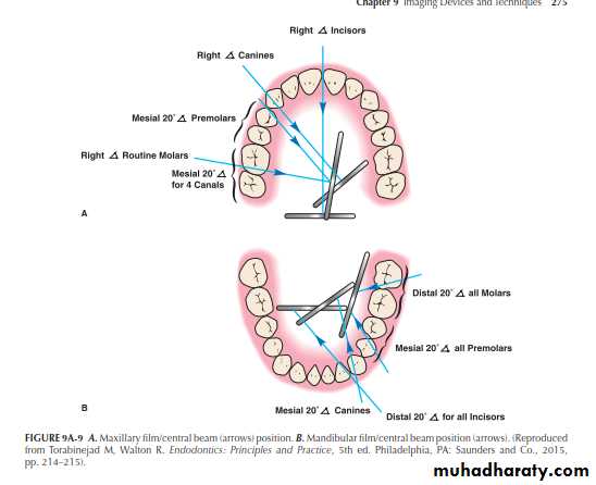
Horizontal Cone Angulations
For working and/or interpretive diagnostic radiographs, the following cone angles are preferred:
1. Maxillary anterior teeth (straight facial).
2. Maxillary premolars and molars (mesial angle)
3. Mandibular incisor teeth (distal angle).
4. Mandibular canines (mesial angle).
5. Mandibular premolars (mesial).
6. Mandibular molars (distal)..
UNIVERSITY OF MOSUL
COLLEGE OF DENTISTRY2020-2021
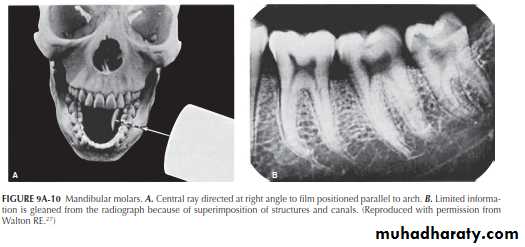
Mandibular Molars
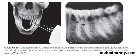
Through the Walton projection (SLOB) , however, the roots will “open up.
”
Mandibular Molars
”This is done by directing the central beam 20° to 30° from either the distal or the mesial (Figure 9A-11A).By applying Ingle’s rule (MBD: project the central beam from the mesial ), the buccal canals are toward the distal , the lingual canals toward the mesial .
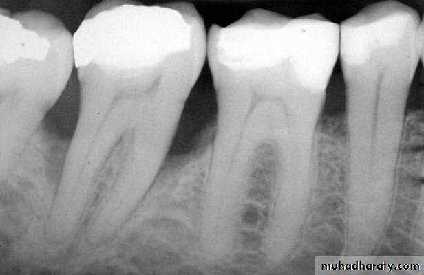
Another point concerns a frequent mistake in “reading” periapical radiographs.
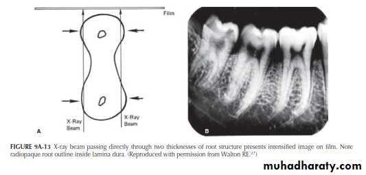
Roots containing two canals are often hourglass shaped. When an X-ray beam passes directly through this structure (center image), the buccal and lingual portions of theroot are in the same path (arrows). These will change with distal and mesial projection. Because a double thickness of tooth structure is penetrated by the X-rays, it is seen in
the film as a radiopaque root outline in close contact with the lamina dura .
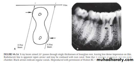
By aiming the cone 20° from the mesial, however, the central beam passes through the hourglass-shaped root at an angle (Figure 9A-14). In this case, the two thicknesses of the root are projected separately onto the film. Because less tooth structure is penetrated by the X-ray, the image on the film is less dense. A radiolucent line is clearly seen (open arrow). This radiolucent line can be erroneously interpreted as a canal. By following up the length of the line, instead of entering the pulp chamber, the line can be traced to the gingival surface of the root; this is the PDL space. This simple interpretive error can easily lead to gross mistakes.
Mandibular Premolars
The importance of varying the horizontal angulation for mandibular premolars is demonstrated in Figure 9A-15A. The central beam is directed at a right angle to the film. What appears to be a single straight canal is discernible in each premolar (Figure 9A-15B).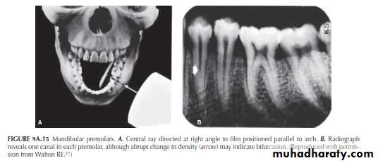
Mandibular Premolars
There is an indication, however, in the image of the first premolar that the canal might bifurcate at the point of the abrupt change (“fast break”) in density (arrow). Directing the central ray 20° from the mesial in the first premolar (Figure 9A-16A) causes the bifurcation to separate into two canals (Figure 9A-16B). The tapering outline of the tooth, seen in both projections, would indicate, on the other hand, that the two canals undoubtedly rejoin to form a common canal at the apex. In both the right-angle and 20° variance projections, the second premolar appears as a single canal.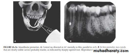
Maxillary Molars
Maxillary molars are consistently the most difficult to radiograph because of• their more complicated root and pulp anatomy,
• the frequent superimposition of portions of the roots on each other, (
• the superimposition of bony structures (sinus floor, zygomatic process) on root structures, and
• the shape and depth of the palate.
Each of these, singly or in combination, can be a major impediment.
Maxillary Molars
As is true of the mandible, the complex root anatomy and superimpositions may be dealt with by varying the horizontal angulations. Film placement must be parallel to the median raphe, not to the posterior maxillary arch. The standard right-angle projection for a maxillary first molar, illustrated in Figure 9A-17A, produces the image seen in Figure 9A-17B, where in the zygomatic process is superimposed on the apex of the palatal root (arrow) and the distobuccal root appears to overlie the palatal root. The sinus floor is also superimposed on the apices of both the first and second molars.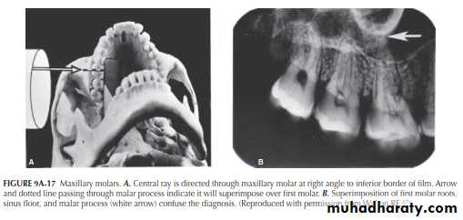
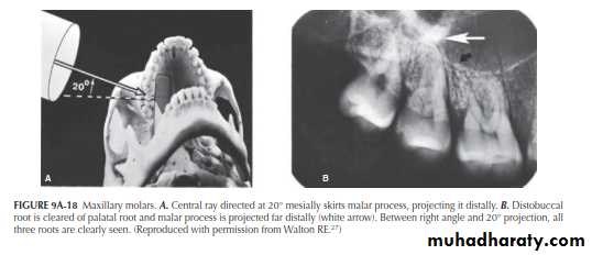
When the horizontal angulation is varied by 20° to the mesial (Figure 9A-18A), the zygomatic process is
“moved” to the distal of the first molar and the distobuccal root is cleared of the palatal root (Figure 9A-18B, arrows). The mesial projection also better “opens” the mesiobuccal root to demonstrate both canals.
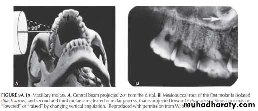
The opposite projection can also be used to isolate the mesiobuccal root of the first molar, that is, the central ray may be projected from 20° distal to the right angle (Figure 9A-19A). Although this projection distorts the shape of the mesiobuccal root, it also isolates it (Figure 9A-19B), so that the canal is readily discernible (arrow). In addition, the zygomatic process is moved completely away from any root
structure, including the second molar. The same technique illustrated here for the maxillary first molar can be applied to the second or third molars by directing the central beam at a horizontal variance through those teeth.
Maxillary Premolars
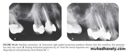
Variance in the horizontal projection has great value in maxillary premolar radiography, particularly for the first premolar, that generally has two roots and canals, but sometimes three. The clinical efficacy of the Walton (SLOB) technique is well illustrated in Figure 9A-20 The right-angle horizontal projection produces the single canal image seen in Figure9A-20A. By varying the angulation by 20°, however, thetwo canals are separated (Figure 9A-20B), giving an unobstructed view of the obturation quality in both canals.
Mandibular Anterior Teeth
Aberrations in canal anatomy in the mandibular anterior teeth are not uncommon. Variance of the horizontal X-ray projections in this region will bring out the differences. Figure 9A-21A illustrates the standard X-ray projection bisecting the film held parallel to the arch. The incisor teeth appear to have single canals. However, a deep single canal is seen in the distorted canine image (Figure 9A-21B).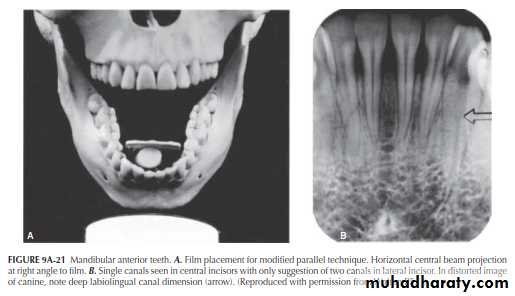
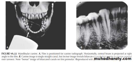
By varying the film placement and projecting directly through the canine, as seen in Figure 9A-22A (about 30° variance for the incisors), separate canals appear in the incisors (Figure 9A-22B, arrow); the canals join at the apex. This would be expected. However, when viewing the tapered incisor roots seen in both horizontal projections, the roots are far too narrow to support two separate canals and foramina. Once again, the abrupt change in canal radiodensity in the premolars (arrow) indicates a canal bifurcation.
UNIVERSITY OF MOSUL
COLLEGE OF DENTISTRY2020-2021
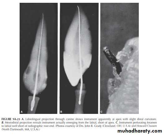
Maxillary Anterior Teeth
Although canal or root aberrations appear less frequently in the maxillary anterior teeth, root curvature in the maxillary lateral incisors is a particularly vexing problem. Also for example, how difficult it is to determine when foramina exit to the labial or lingual. Their radiographs of extracted teeth matched with photographs of instrument perforation short of the apex are a warning to all (Figure 9A-23).
UNIVERSITY OF MOSUL
COLLEGE OF DENTISTRY
2020-2021
disagreement was found in the interpretation of radiographs
by different evaluators regarding the presence of periapical
radiolucencies, as well as, the same evaluator interpreting
the same image over time. Limitations of radiographic
interpretation have been minimized by exposing multiple
radiographs, from different angulations, to improve visuali-
zation of changes in an area in question
UNIVERSITY OF MOSUL
COLLEGE OF DENTISTRY2020-2021
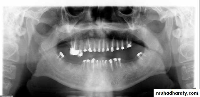
Panoramic radiography also represents a 2-D image of 3-D anatomy that again has some limitations It also contains artifacts and unique distortions that can further complicate panoramic interpretation.
UNIVERSITY OF MOSUL
COLLEGE OF DENTISTRY2020-2021
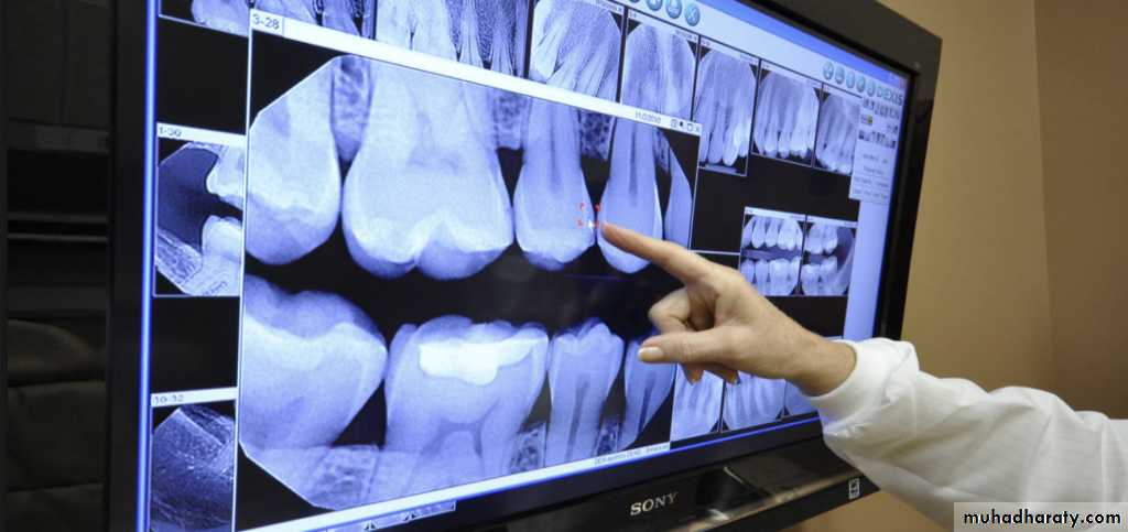
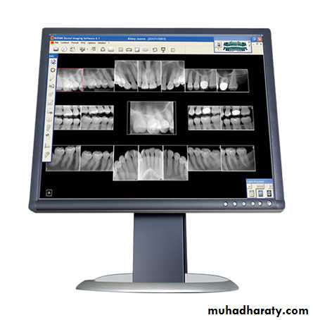
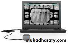
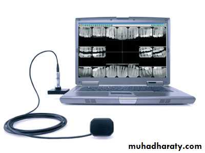
Digital radiography
has allowed for image enhancement with control of parameters such as brightness, contrast, magnification, inversion, color, and resolution AND allow storge. This is a clear advantage over traditional radiography. The introduction of digital radiography has improved the speed of image acquisition and potentially reduced patient exposure to radiation. Nevertheless, the overall limitations of conventional radiography and 2-D imaging remain inher- ently present
UNIVERSITY OF MOSUL
COLLEGE OF DENTISTRY2020-2021
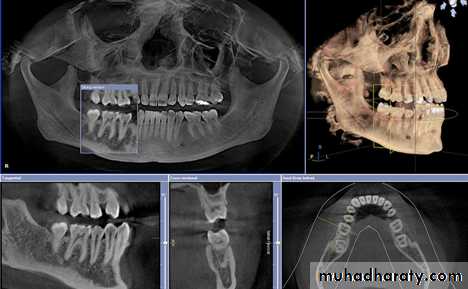
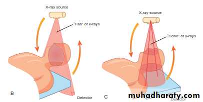
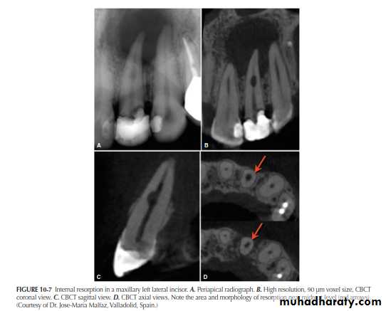
THE ADVENT OF CBCT AND THE THIRD PLANE OF VISUALIZATON
CBCT has been optimized for dental applications. Smaller fields of view and higher resolution scans appear to be ideal for endodontic use and may impact the nature of endodotic practice and radiographic decision-making in the near Future. One of the disadvantages of CBCT use is cost and access to the technology. However, with time, costs should continue to decrease and access to increase

UNIVERSITY OF MOSUL
COLLEGE OF DENTISTRY
2020-2021
. Other areas of controversy and concern are radiation exposure to patients, the training needed to operate and interpret the scans optimally, as well as the amount of time necessary to evaluate them. Like all radiographic studies, CBCT imaging and diagnostic accuracy rely heavily on parameters such as image quality, viewing conditions, and observer performance characteristics. Interpretation of the collected volumes, potentially affecting treatment planning, can be a challenge with respect to defining normal versus
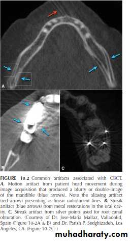
pathological conditions. Hardware and software parameters also heavily influence image quality and resolution. CBCT, like other radiographic modalities, can also contain artifacts and noise that make evaluation and interpretation difficult in some cases. Common artifacts to be aware of include noise, aliasing, scatter and beam hardening, motion artifact, and finally streak artifact that usually results from metal or high density restorations in the oral cavity such as metal crowns, orthodontic appliances, amalgam fillings, separated instruments and tooth, and root canal filling materials
UNIVERSITY OF MOSUL
COLLEGE OF DENTISTRY2020-2021
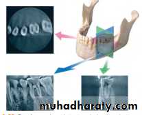
A major advantage of CBCT is the visualization of anatomic
structures in three planes, generally referred to as coronal, axial (transverse), and sagittal reconstructions. CBCT technology also allows for panoramic and oblique reconstructions in addition to anatomic-specific reformatting such as temporomandibular joint (TMJ) improved the sensitivity and specificity of accurately detecting lesions or conditions affecting the jaws
UNIVERSITY OF MOSUL
COLLEGE OF DENTISTRY2020-2021
Currently, CBCT imaging is generally recommended for endodontic cases in which conventional dental radiographs may not yield adequate information
UNIVERSITY OF MOSUL
COLLEGE OF DENTISTRY
2020-2021
UNIVERSITY OF MOSUL
COLLEGE OF DENTISTRY2020-2021
UNIVERSITY OF MOSUL
COLLEGE OF DENTISTRY2020-2021
For these reasons, it is important not to exclude the possibility of pulpal pathosis in
situations in which there are no radiographic changes
They are obviously essential, but are frequently overused and/ or misinterpreted.
UNIVERSITY OF MOSUL
COLLEGE OF DENTISTRY
THE END
2020-2021
Hope to you life without apical pathosis