
PRINCIPLES OF REMOTE SENSING
Shefali Aggarwal
Photogrammetry and Remote Sensing Division
Indian Institute of Remote Sensing, Dehra Dun
Abstract : Remote sensing is a technique to observe the earth surface or the
atmosphere from out of space using satellites (space borne) or from the air using
aircrafts (airborne). Remote sensing uses a part or several parts of the
electromagnetic spectrum. It records the electromagnetic energy reflected or emitted
by the earth’s surface. The amount of radiation from an object (called radiance) is
influenced by both the properties of the object and the radiation hitting the object
(irradiance). The human eyes register the solar light reflected by these objects and
our brains interpret the colours, the grey tones and intensity variations. In remote
sensing various kinds of tools and devices are used to make electromagnetic radiation
outside this range from 400 to 700 nm visible to the human eye, especially the
near infrared, middle-infrared, thermal-infrared and microwaves.
Remote sensing imagery has many applications in mapping land-use and cover,
agriculture, soils mapping, forestry, city planning, archaeological investigations,
military observation, and geomorphological surveying, land cover changes,
deforestation, vegetation dynamics, water quality dynamics, urban growth, etc. This
paper starts with a brief historic overview of remote sensing and then explains the
various stages and the basic principles of remotely sensed data collection mechanism.
INTRODUCTION
R
emote sensing (RS), also called earth observation, refers to obtaining
information about objects or areas at the Earth’s surface without being
in direct contact with the object or area. Humans accomplish this task with
aid of eyes or by the sense of smell or hearing; so, remote sensing is day-to-
day business for people. Reading the newspaper, watching cars driving in front
of you are all remote sensing activities. Most sensing devices record information
about an object by measuring an object’s transmission of electromagnetic energy
from reflecting and radiating surfaces.
Satellite Remote Sensing and GIS Applications in Agricultural Meteorology
pp. 23-38

24
Principles of Remote Sensing
Remote sensing techniques allow taking images of the earth surface in
various wavelength region of the electromagnetic spectrum (EMS). One of the
major characteristics of a remotely sensed image is the wavelength region it
represents in the EMS. Some of the images represent reflected solar radiation
in the visible and the near infrared regions of the electromagnetic spectrum,
others are the measurements of the energy emitted by the earth surface itself
i.e. in the thermal infrared wavelength region. The energy measured in the
microwave region is the measure of relative return from the earth’s surface,
where the energy is transmitted from the vehicle itself. This is known as active
remote sensing, since the energy source is provided by the remote sensing
platform. Whereas the systems where the remote sensing measurements
depend upon the external energy source, such as sun are referred to as passive
remote sensing systems.
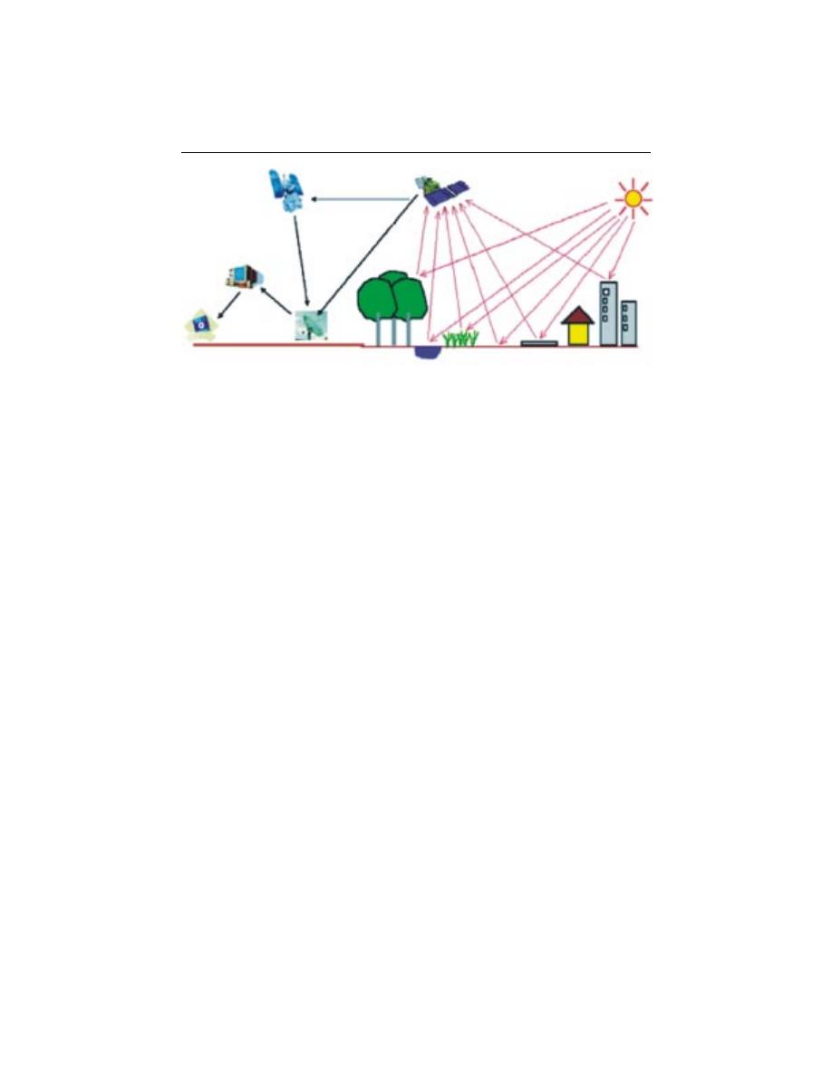
PRINCIPLES OF REMOTE SENSING
Detection and discrimination of objects or surface features means detecting
and recording of radiant energy reflected or emitted by objects or surface
material (Fig. 1). Different objects return different amount of energy in different
bands of the electromagnetic spectrum, incident upon it. This depends on
the property of material (structural, chemical, and physical), surface roughness,
angle of incidence, intensity, and wavelength of radiant energy.
The Remote Sensing is basically a multi-disciplinary science which includes
a combination of various disciplines such as optics, spectroscopy, photography,
computer, electronics and telecommunication, satellite launching etc. All these
technologies are integrated to act as one complete system in itself, known as
Remote Sensing System. There are a number of stages in a Remote Sensing
process, and each of them is important for successful operation.
Stages in Remote Sensing
•
Emission of electromagnetic radiation, or EMR (sun/self- emission)
•
Transmission of energy from the source to the surface of the earth, as well
as absorption and scattering
•
Interaction of EMR with the earth’s surface: reflection and emission
•
Transmission of energy from the surface to the remote sensor
•
Sensor data output
Shefali Aggarwal
25
•
Data transmission, processing and analysis
What we see
At temperature above absolute zero, all objects radiate electromagnetic
energy by virtue of their atomic and molecular oscillations. The total amount
of emitted radiation increases with the body’s absolute temperature and peaks
at progressively shorter wavelengths. The sun, being a major source of energy,
radiation and illumination, allows capturing reflected light with conventional
(and some not-so-conventional) cameras and films.
The basic strategy for sensing electromagnetic radiation is clear. Everything
in nature has its own unique distribution of reflected, emitted and absorbed
radiation. These spectral characteristics, if ingeniously exploited, can be used
to distinguish one thing from another or to obtain information about shape,
size and other physical and chemical properties.
Modern Remote Sensing Technology versus Conventional Aerial Photography
The use of different and extended portions of the electromagnetic
spectrum, development in sensor technology, different platforms for remote
sensing (spacecraft, in addition to aircraft), emphasize on the use of spectral
information as compared to spatial information, advancement in image
processing and enhancement techniques, and automated image analysis in
addition to manual interpretation are points for comparison of conventional
aerial photography with modern remote sensing system.
Figure 1: Remote Sensing process
Built-up Area
Sun
Distribute for Analysis
Pre-Process and Archive
Satellite
Reflected
Solar Radiation
F o r e s t
Grass
Water
Bare Soil Paved
Road
Atmosphere
Down Link

26
Principles of Remote Sensing
During early half of twentieth century, aerial photos were used in military
surveys and topographical mapping. Main advantage of aerial photos has been
the high spatial resolution with fine details and therefore they are still used
for mapping at large scale such as in route surveys, town planning,
construction project surveying, cadastral mapping etc. Modern remote sensing
system provide satellite images suitable for medium scale mapping used in
natural resources surveys and monitoring such as forestry, geology, watershed
management etc. However the future generation satellites are going to provide
much high-resolution images for more versatile applications.
HISTORIC OVERVIEW
In 1859 Gaspard Tournachon took an oblique photograph of a small village
near Paris from a balloon. With this picture the era of earth observation and
remote sensing had started. His example was soon followed by other people
all over the world. During the Civil War in the United States aerial
photography from balloons played an important role to reveal the defence
positions in Virginia (Colwell, 1983). Likewise other scientific and technical
developments this Civil War time in the United States speeded up the
development of photography, lenses and applied airborne use of this
technology. Table 1 shows a few important dates in the development of remote
sensing.
The next period of fast development took place in Europe and not in the
United States. It was during World War I that aero planes were used on a
large scale for photoreconnaissance. Aircraft proved to be more reliable and
more stable platforms for earth observation than balloons. In the period
between World War I and World War II a start was made with the civilian
use of aerial photos. Application fields of airborne photos included at that
time geology, forestry, agriculture and cartography. These developments lead
to much improved cameras, films and interpretation equipment. The most
important developments of aerial photography and photo interpretation took
place during World War II. During this time span the development of other
imaging systems such as near-infrared photography; thermal sensing and radar
took place. Near-infrared photography and thermal-infrared proved very
valuable to separate real vegetation from camouflage. The first successful
airborne imaging radar was not used for civilian purposes but proved valuable
for nighttime bombing. As such the system was called by the military ‘plan
position indicator’ and was developed in Great Britain in 1941.

Shefali Aggarwal
27
After the wars in the 1950s remote sensing systems continued to evolve
from the systems developed for the war effort. Colour infrared (CIR)
photography was found to be of great use for the plant sciences. In 1956
Colwell conducted experiments on the use of CIR for the classification and
recognition of vegetation types and the detection of diseased and damaged or
stressed vegetation. It was also in the 1950s that significant progress in radar
technology was achieved.
Table1: Milestones in the History of Remote Sensing
1800
Discovery of Infrared by Sir W. Herschel
1839
Beginning of Practice of Photography
1847
Infrared Spectrum Shown by J.B.L. Foucault
1859
Photography from Balloons
1873
Theory of Electromagnetic Spectrum by J.C. Maxwell
1909
Photography from Airplanes
1916
World War I: Aerial Reconnaissance
1935
Development of Radar in Germany
1940
WW II: Applications of Non-Visible Part of EMS
1950
Military Research and Development
1959
First Space Photograph of the Earth (Explorer-6)
1960
First TIROS Meteorological Satellite Launched
1970
Skylab Remote Sensing Observations from Space
1972
Launch Landsat-1 (ERTS-1) : MSS Sensor
1972
Rapid Advances in Digital Image Processing
1982
Launch of Landsat -4 : New Generation of Landsat Sensors: TM
1986
French Commercial Earth Observation Satellite SPOT
1986
Development Hyperspectral Sensors
1990
Development High Resolution Space borne Systems
First Commercial Developments in Remote Sensing
1998
Towards Cheap One-Goal Satellite Missions
1999
Launch EOS : NASA Earth Observing Mission
1999
Launch of IKONOS, very high spatial resolution sensor system
28
Principles of Remote Sensing
ELECTROMAGNETIC RADIATION AND THE ELECTROMAGNETIC
SPECTRUM
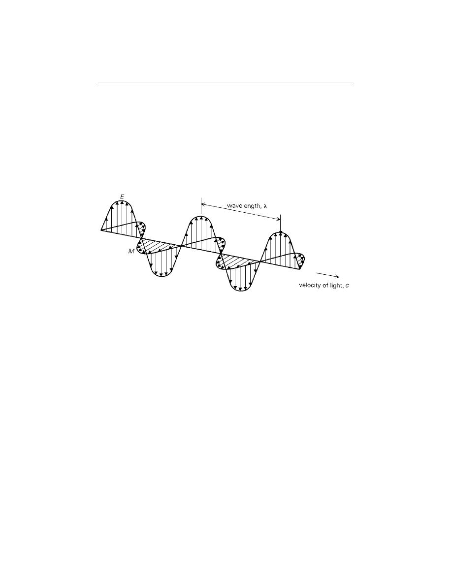
EMR is a dynamic form of energy that propagates as wave motion at a velocity
of c = 3 x 10
10
cm/sec. The parameters that characterize a wave motion are
wavelength (
λ
), frequency (
ν
) and velocity (c) (Fig. 2). The relationship
between the above is
c =
νλ
.
Figure 2: Electromagnetic wave. It has two components, Electric field E and Magnetic
field M, both perpendicular to the direction of propagation
Electromagnetic energy radiates in accordance with the basic wave theory.
This theory describes the EM energy as travelling in a harmonic sinusoidal
fashion at the velocity of light. Although many characteristics of EM energy
are easily described by wave theory, another theory known as particle theory
offers insight into how electromagnetic energy interacts with matter. It suggests
that EMR is composed of many discrete units called photons/quanta. The
energy of photon is
Q = hc /
λ
= h
ν
Where
Q is the energy of quantum,
h = Planck’s constant

Shefali Aggarwal
29
This region is beyond the violet portion of the visible
wavelength, and hence its name. Some earth’s surface
material primarily rocks and minerals emit visible UV
radiation. However UV radiation is largely scattered
by earth’s atmosphere and hence not used in field of
remote sensing.
This is the light, which our eyes can detect. This is
the only portion of the spectrum that can be
associated with the concept of color. Blue Green and
Red are the three primary colors of the visible
spectrum. They are defined as such because no single
primary color can be created from the other two, but
all other colors can be formed by combining the
three in various proportions. The color of an object
is defined by the color of the light it reflects.
Wavelengths longer than the red portion of the
visible spectrum are designated as the infrared
spectrum. British Astronomer William Herschel
discovered this in 1800. The infrared region can be
divided into two categories based on their radiation
properties.
Reflected IR (.7
µ
m - 3.0
µ
m) is used for remote
sensing. Thermal IR (3
µ
m - 35
µ
m) is the radiation
emitted from earth’s surface in the form of heat and
used for remote sensing.
This is the longest wavelength used in remote sensing.
The shortest wavelengths in this range have
properties similar to thermal infrared region. The
main advantage of this spectrum is its ability to
penetrate through clouds.
This is the longest portion of the spectrum mostly
used for commercial broadcast and meteorology.
Table 2: Principal Divisions of the Electromagnetic Spectrum
Wavelength
Description
Gamma rays
Gamma rays
X-rays
X-rays
Ultraviolet (UV) region
0.30
µ
m - 0.38
µ
m
(1
µ
m = 10
-6
m)
Visible Spectrum
0.4
µ
m - 0.7
µ
m
Violet 0.4
µ
m -0.446
µ
m
Blue 0.446
µ
m -0.5
µ
m
Green 0.5
µ
m - 0.578
µ
m
Yellow 0.578
µ
m - 0.592
µ
m
Orange 0.592
µ
m - 0.62
µ
m
Red 0.62
µ
m -0.7
µ
m
Infrared (IR) Spectrum
0.7
µ
m – 100
µ
m
Microwave Region
1 mm - 1 m
Radio Waves
(>1 m)
30
Principles of Remote Sensing
Types of Remote Sensing
Remote sensing can be either passive or active. ACTIVE systems have their
own source of energy (such as RADAR) whereas the PASSIVE systems depend
upon external source of illumination (such as SUN) or self-emission for remote
sensing.
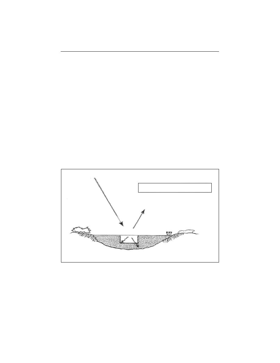
INTERACTION OF EMR WITH THE EARTH’S SURFACE
Radiation from the sun, when incident upon the earth’s surface, is either
reflected by the surface, transmitted into the surface or absorbed and emitted
by the surface (Fig. 3). The EMR, on interaction, experiences a number of
changes in magnitude, direction, wavelength, polarization and phase. These
changes are detected by the remote sensor and enable the interpreter to obtain
useful information about the object of interest. The remotely sensed data
contain both spatial information (size, shape and orientation) and spectral
information (tone, colour and spectral signature).
Figure 3: Interaction of Energy with the earth’s surface. ( source: Liliesand & Kiefer, 1993)
From the viewpoint of interaction mechanisms, with the object-visible and
infrared wavelengths from 0.3
µ
m to 16
µ
m can be divided into three regions.
The spectral band from 0.3
µ
m to 3
µ
m is known as the reflective region. In
this band, the radiation sensed by the sensor is that due to the sun, reflected
E
R
(
λ
) = Reflected energy
E
I
(
λ
) = E
R
(
λ
) + E
A
(
λ
) + E
T
(
λ
)
E
I
(
λ
) = Incident energy
E
A
(
λ
) = Absorbed energy
E
T
(
λ
) = Transmitted energy
Shefali Aggarwal
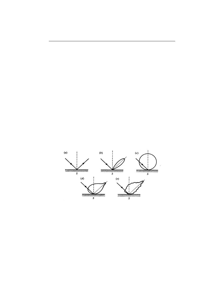
31
Figure 4. Different types of scattering surfaces (a) Perfect specular reflector (b) Near perfect
specular reflector (c) Lambertain (d) Quasi-Lambertian (e) Complex.
by the earth’s surface. The band corresponding to the atmospheric window
between 8
µ
m and 14
µ
m is known as the thermal infrared band. The energy
available in this band for remote sensing is due to thermal emission from the
earth’s surface. Both reflection and self-emission are important in the
intermediate band from 3
µ
m to 5.5
µ
m.
In the microwave region of the spectrum, the sensor is radar, which is an
active sensor, as it provides its own source of EMR. The EMR produced by
the radar is transmitted to the earth’s surface and the EMR reflected (back
scattered) from the surface is recorded and analyzed. The microwave region
can also be monitored with passive sensors, called microwave radiometers, which
record the radiation emitted by the terrain in the microwave region.
Reflection
Of all the interactions in the reflective region, surface reflections are the
most useful and revealing in remote sensing applications. Reflection occurs
when a ray of light is redirected as it strikes a non-transparent surface. The
reflection intensity depends on the surface refractive index, absorption
coefficient and the angles of incidence and reflection (Fig. 4).
Transmission
Transmission of radiation occurs when radiation passes through a
substance without significant attenuation. For a given thickness, or depth of
a substance, the ability of a medium to transmit energy is measured as
transmittance (
τ
).

32
Principles of Remote Sensing
Transmitted radiation
τ
=———————————
Incident radiation
Spectral Signature
Spectral reflectance, [
ρ
(
λ
)], is the ratio of reflected energy to incident
energy as a function of wavelength. Various materials of the earth’s surface have
different spectral reflectance characteristics. Spectral reflectance is responsible
for the color or tone in a photographic image of an object. Trees appear green
because they reflect more of the green wavelength. The values of the spectral
reflectance of objects averaged over different, well-defined wavelength intervals
comprise the spectral signature of the objects or features by which they can
be distinguished. To obtain the necessary ground truth for the interpretation
of multispectral imagery, the spectral characteristics of various natural objects
have been extensively measured and recorded.
The spectral reflectance is dependent on wavelength, it has different values
at different wavelengths for a given terrain feature. The reflectance
characteristics of the earth’s surface features are expressed by spectral reflectance,
which is given by:
ρ
(
λ
) = [E
R
(
λ
) / E
I
(
λ
)] x 100
Where,
ρ
(
λ
)
= Spectral reflectance (reflectivity) at a particular wavelength.
E
R
(
λ
) = Energy of wavelength reflected from object
E
I
(
λ
)
= Energy of wavelength incident upon the object
The plot between
ρ
(
λ
) and
λ
is called a spectral reflectance curve. This
varies with the variation in the chemical composition and physical conditions
of the feature, which results in a range of values. The spectral response patterns
are averaged to get a generalized form, which is called generalized spectral
response pattern for the object concerned. Spectral signature is a term used
for unique spectral response pattern, which is characteristic of a terrain feature.
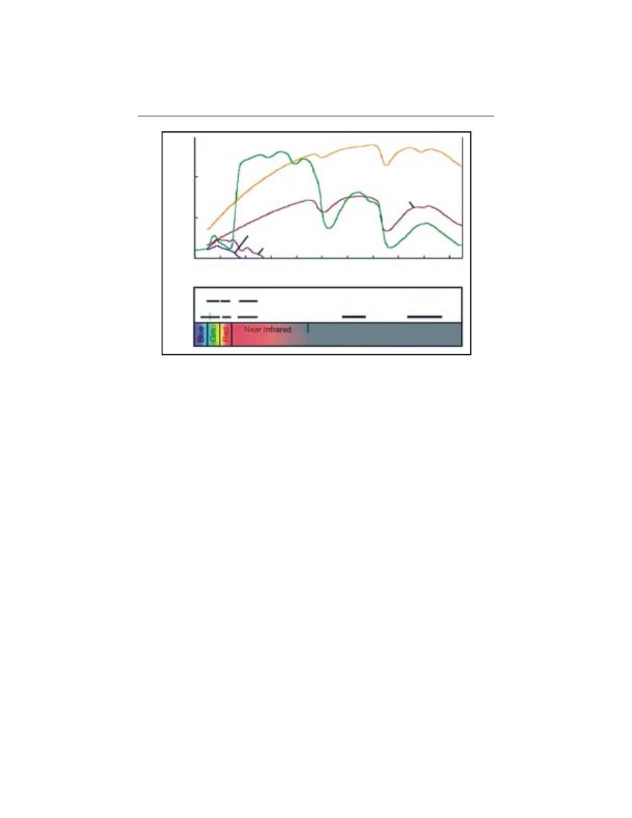
Figure 5 shows a typical reflectance curves for three basic types of earth surface
features, healthy vegetation, dry bare soil (grey-brown and loamy) and clear
lake water.
Shefali Aggarwal
33
Reflectance Characteristics of Earth’s Cover types
The spectral characteristics of the three main earth surface features are
discussed below :
Vegetation: The spectral characteristics of vegetation vary with wavelength.
Plant pigment in leaves called chlorophyll strongly absorbs radiation in the
red and blue wavelengths but reflects green wavelength. The internal structure
of healthy leaves acts as diffuse reflector of near infrared wavelengths.
Measuring and monitoring the near infrared reflectance is one way that
scientists determine how healthy particular vegetation may be.
Water: Majority of the radiation incident upon water is not reflected but is
either absorbed or transmitted. Longer visible wavelengths and near infrared
radiation is absorbed more by water than by the visible wavelengths. Thus
water looks blue or blue green due to stronger reflectance at these shorter
wavelengths and darker if viewed at red or near infrared wavelengths. The
factors that affect the variability in reflectance of a water body are depth of
water, materials within water and surface roughness of water.
Soil: The majority of radiation incident on a soil surface is either reflected or
absorbed and little is transmitted. The characteristics of soil that determine
Figure 5. Typical Spectral Reflectance curves for vegetation, soil and water
Vegetation
Dry soil
(5% water)
Wet soil
(20% water)
Clear lake water
Turbid river water
0.4 0.6 0.8 1.0 1.2 1.4 1.6 1.8 2.0 2.2 2.4
Wavelength (micrometers)
SPOT XS Multispectral Bands
Landsat TM Bands
5
7
1 2 3
1 2 3 4
60
40
20
0
Middle Infrared
Reflected Infrared
R
e
fl
e
c
tan
c
e (
%
)

34
Principles of Remote Sensing
its reflectance properties are its moisture content, organic matter content,
texture, structure and iron oxide content. The soil curve shows less peak and
valley variations. The presence of moisture in soil decreases its reflectance.
By measuring the energy that is reflected by targets on earth’s surface over
a variety of different wavelengths, we can build up a spectral signature for
that object. And by comparing the response pattern of different features we
may be able to distinguish between them, which we may not be able to do if
we only compare them at one wavelength. For example, Water and Vegetation
reflect somewhat similarly in the visible wavelength but not in the infrared.
INTERACTIONS WITH THE ATMOSPHERE
The sun is the source of radiation, and electromagnetic radiation (EMR)
from the sun that is reflected by the earth and detected by the satellite or
aircraft-borne sensor must pass through the atmosphere twice, once on its
journey from the sun to the earth and second after being reflected by the
surface of the earth back to the sensor. Interactions of the direct solar radiation
and reflected radiation from the target with the atmospheric constituents
interfere with the process of remote sensing and are called as “Atmospheric
Effects”.
The interaction of EMR with the atmosphere is important to remote
sensing for two main reasons. First, information carried by EMR reflected/
emitted by the earth’s surface is modified while traversing through the
atmosphere. Second, the interaction of EMR with the atmosphere can be used
to obtain useful information about the atmosphere itself.
The atmospheric constituents scatter and absorb the radiation modulating
the radiation reflected from the target by attenuating it, changing its spatial
distribution and introducing into field of view radiation from sunlight
scattered in the atmosphere and some of the energy reflected from nearby
ground area. Both scattering and absorption vary in their effect from one part
of the spectrum to the other.
The solar energy is subjected to modification by several physical processes
as it passes the atmosphere, viz.
1) Scattering; 2) Absorption, and 3) Refraction

Shefali Aggarwal
35
Atmospheric Scattering
Scattering is the redirection of EMR by particles suspended in the
atmosphere or by large molecules of atmospheric gases. Scattering not only
reduces the image contrast but also changes the spectral signature of ground
objects as seen by the sensor. The amount of scattering depends upon the
size of the particles, their abundance, the wavelength of radiation, depth of
the atmosphere through which the energy is traveling and the concentration
of the particles. The concentration of particulate matter varies both in time
and over season. Thus the effects of scattering will be uneven spatially and
will vary from time to time.
Theoretically scattering can be divided into three categories depending
upon the wavelength of radiation being scattered and the size of the particles
causing the scattering. The three different types of scattering from particles
of different sizes are summarized below:
Scattering
Wavelength
Approximate
Kinds
process
dependence
of particles
particle size
Selective
z
Rayleigh
λ
-4
< 1
µ
m
Air molecules
z
Mie
λ
o to
λ
-4
0.1 to 10
µ
m
Smoke, haze
z
Non-selective
λ
o
> 10
µ
m
Dust, fog, clouds
Rayleigh Scattering
Rayleigh scattering predominates where electromagnetic radiation interacts
with particles that are smaller than the wavelength of the incoming light. The
effect of the Rayleigh scattering is inversely proportional to the fourth power
of the wavelength. Shorter wavelengths are scattered more than longer
wavelengths. In the absence of these particles and scattering the sky would
appear black. In the context of remote sensing, the Rayleigh scattering is the
most important type of scattering. It causes a distortion of spectral
characteristics of the reflected light when compared to measurements taken
on the ground.

36
Principles of Remote Sensing
Mie Scattering
Mie scattering occurs when the wavelength of the incoming radiation is
similar in size to the atmospheric particles. These are caused by aerosols: a
mixture of gases, water vapor and dust. It is generally restricted to the lower
atmosphere where the larger particles are abundant and dominates under
overcast cloud conditions. It influences the entire spectral region from ultra
violet to near infrared regions.
Non-selective Scattering
This type of scattering occurs when the particle size is much larger than
the wavelength of the incoming radiation. Particles responsible for this effect
are water droplets and larger dust particles. The scattering is independent of
the wavelength, all the wavelength are scattered equally. The most common
example of non-selective scattering is the appearance of clouds as white. As
cloud consist of water droplet particles and the wavelengths are scattered in
equal amount, the cloud appears as white.
Occurrence of this scattering mechanism gives a clue to the existence of
large particulate matter in the atmosphere above the scene of interest which
itself is a useful data. Using minus blue filters can eliminate the effects of the
Rayleigh component of scattering. However, the effect of heavy haze i.e. when
all the wavelengths are scattered uniformly, cannot be eliminated using haze
filters. The effects of haze are less pronounced in the thermal infrared region.
Microwave radiation is completely immune to haze and can even penetrate
clouds.
Atmospheric Absorption
The gas molecules present in the atmosphere strongly absorb the EMR
passing through the atmosphere in certain spectral bands. Mainly three gases
are responsible for most of absorption of solar radiation, viz. ozone, carbon
dioxide and water vapour. Ozone absorbs the high energy, short wavelength
portions of the ultraviolet spectrum (
λ
< 0.24
µ
m) thereby preventing the
transmission of this radiation to the lower atmosphere. Carbon dioxide is
important in remote sensing as it effectively absorbs the radiation in mid and
far infrared regions of the spectrum. It strongly absorbs in the region from
about 13-17.5
µ
m, whereas two most important regions of water vapour
absorption are in bands 5.5 - 7.0
µ
m and above 27
µ
m. Absorption relatively
Shefali Aggarwal
37
reduces the amount of light that reaches our eye making the scene look
relatively duller.
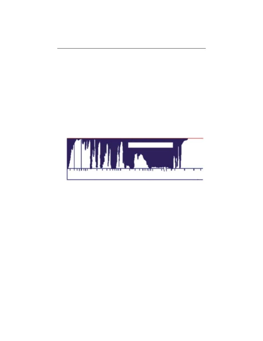
Atmospheric Windows
The general atmospheric transmittance across the whole spectrum of
wavelengths is shown in Figure 6. The atmosphere selectively transmits energy
of certain wavelengths. The spectral bands for which the atmosphere is
relatively transparent are known as atmospheric windows. Atmospheric
windows are present in the visible part (.4
µ
m - .76
µ
m) and the infrared
regions of the EM spectrum. In the visible part transmission is mainly effected
by ozone absorption and by molecular scattering. The atmosphere is transparent
again beyond about
λ
= 1mm, the region used for microwave remote sensing.
Figure 6 : Atmospheric windows
Refraction
The phenomenon of refraction, that is bending of light at the contact
between two media, also occurs in the atmosphere as the light passes through
the atmospheric layers of varied clarity, humidity and temperature. These
variations influence the density of atmospheric layers, which in turn, causes
the bending of light rays as they pass from one layer to another. The most
common phenomena are the mirage like apparitions sometimes visible in the
distance on hot summer days.
CONCLUSIONS
Remote sensing technology has developed from balloon photography to
aerial photography to multi-spectral satellite imaging. Radiation interaction
characteristics of earth and atmosphere in different regions of electromagnetic
blocking effect of atmosphere
at
m
os
ph
e
ric
tr
an
sm
it
ta
n
c
e
1.0
0.0
m
icr
o
w
av
es
0.3 0.6 1.0 5.0 10 50 100 200 m 1mm 1cm 1m 10m
Wavelength
UV
VI
S
II
IR
VI
IR
TI
R
II
R
V
IIR

38
Principles of Remote Sensing
spectrum are very useful for identifying and characterizing earth and
atmospheric features.
REFERENCES
Campbell, J.B. 1996. Introduction to Remote Sensing. Taylor & Francis, London.
Colwell, R.N. (Ed.) 1983. Manual of Remote Sensing. Second Edition. Vol I: Theory,
Instruments and Techniques. American Society of Photogrammetry and Remote Sensing
ASPRS, Falls Church.
Curran, P.J. 1985. Principles of Remote Sensing. Longman Group Limited, London.
Elachi, C. 1987. Introduction to the Physics and Techniques of Remote Sensing. Wiley Series
in Remote Sensing, New York.
http://www.ccrs.nrcan.gc.ca/ccrs/learn/tutorials/fundam/chapter1/chapter1_1_e.html
Joseph, G. 1996. Imaging Sensors. Remote Sensing Reviews, 13: 257-342.
Lillesand, T.M. and Kiefer, R.1993. Remote Sensing and Image Interpretation. Third Edition
John Villey, New York.
Manual of Remote Sensing. III
rd
Edition. American Society of Photogrammtery and Remote
Sensing.
Sabins, F.F. 1997. Remote Sensing and Principles and Image Interpretation. WH Freeman,
New York.