3)
Experiment
No.
(
Binary & BCD Adder and
Subtractor Circuits
Objective
Understanding
the
characteristics
of
binary
adder,
binary
subtractor
and
BCD
adder
in
the
arithmetic
unit.
duction
Intro
A
binary
adder
is
a
digital
circuit
that
produces
the
arithmetic
sum
of
two
binary
numbers.
It
can
be
constructed
with
full
adders
connected
in
cascade
with
the
output
carry
from
each
full
adder
connected
to
the
input
carry
of
the
next
full
adder
in
the
chain.
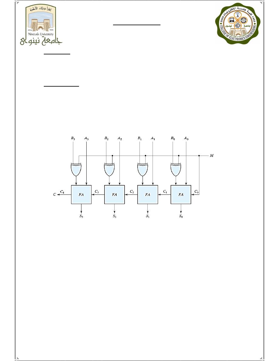
The
binary
addition
and
subtraction
operations
can
be
combined
into
one
circuit
with
one
common
binary
adder
by
including
an
exclusive -OR
gate
with
each
full
adder.
The
mode
input
M
controls
the
operation.
When
M
=
0,
the
circuit
is
an
adder
and
when
M
=
1,
the
circuit
becomes
a
Subtractor.
Binary
adders
can
be
converted
into
BCD
adders .
Since
BCD
has
4
bits
with
the
largest
number
being
9
and
the
largest
4
bit
binary
number
is
equivalent
to
15 ,
there
is
a
difference
of
6
between
the
binary
and
the
BCD
adder .
Six
must
be
added
when
binary
adders
are
used
for
BCD
adding
on
the
following
conditions:
1.
When
there
is
a
carry
in
the
result.
2.
When
the
sum
is
larger
than
9.
Therefore,
six
must
be
added
according
to
the
following
equation:
Cn=CY+
S8.S4+
S8.S2
BCD Adder
Prepared By: Mohammed N. Y. Almaged
Systems & Control Engineering Dept.
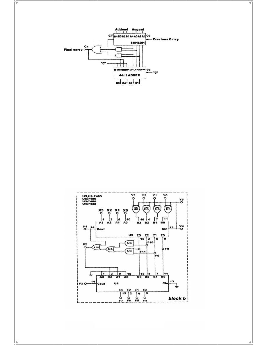
A.
Binary
Adder
:
U
5
on
block
b
of
module
KL-33004
is
used
as
a
4-bit
adder .
Connect
input
Y
5
to
'0',
so
the
XOR
gates
U6a - U6d,
which
are
connected
to
Y
0
Y
3
,
will
act
as
buffers .
Connect
inputs
X
3
X
0
(addend),
Y
3
-Y
0
(augend)
to
DIP
Switches
DIP
2.0 - 2.
3
and
DIP
1.0 - 1.3
respectively.
Then
connect
F1,
F11,
F10,
F9,
F8,
to
L5
-
L.
Follow
input
sequences
in
table
(3-1)
to
record
the
output
0
X
1
X
2
X
3
X=X
0
Y
1
Y
2
Y
3
Y=Y
Fig.(5-9)
Fig.(3-1)
BCD Adder
Equipment Required: KL-31001 Digital Logic lap. Module KL-33004.
INPUT
OUTPUT
X
Y
F1
F11
F10
F9
F8
0 0 1 0
0 1 1 0
Fig.(3-2)
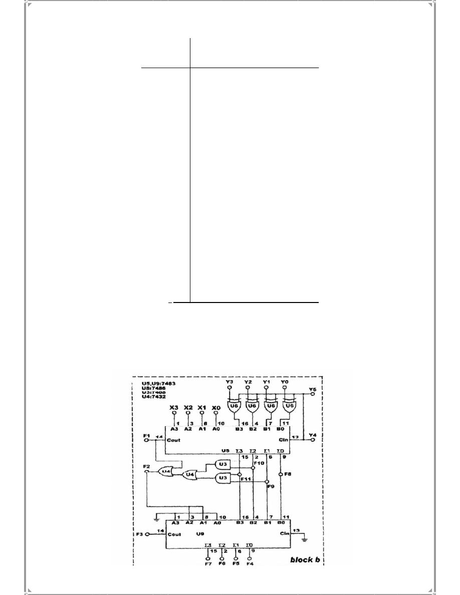
B.
Binary
Subtractor:
Use
U5
on
block
b
of
module
KL-33004,
which
is
shown
in
Fig(
3-2),
to
construct
the
Binay
Subtractor
.
Connect
Y5
to
"1".
Follow
the
input
sequences
in
table
(3- 2)
and
record
the
output
states.
Table(3-1)
0 0 1 1
0 1
1
1
0
1
1
0
0 1 1 1
0 1
0
1
1
0 1
1
0
1
1
0
1
1 1
0
1 0 0
1
1
0
0 1
0
1
1 1
1
1 1
0
1 0 1 0
1
0 1
1
0
1
1
0
1 1 1
0
1 1
1
1
1
0 1
1
1
1
1
0
1
1 1 1
1 1 1
1
1 1 1
1
Output
F1 F11 F10 F9 F8
Input
Y3 Y2 Y1 Y0
X3 X2 X1 X0
0 1 0 0
0 1 0 0
0 0 1 1
0 1 0 0
0 0 1 1
1 0 0 0
0 0 0 1
1 0 0 0
1 0 0 0
1 0 0 1
0 1 1 1
1 0 0 1
0 1 1 0
1 0 1 0
0 1 0 1
1 0 1 0
1 0 1 0
1 0 1 1
0 1 0 1
1 1 1 1
0 1 0 0
0 0 1 1
)
-2
Table(3
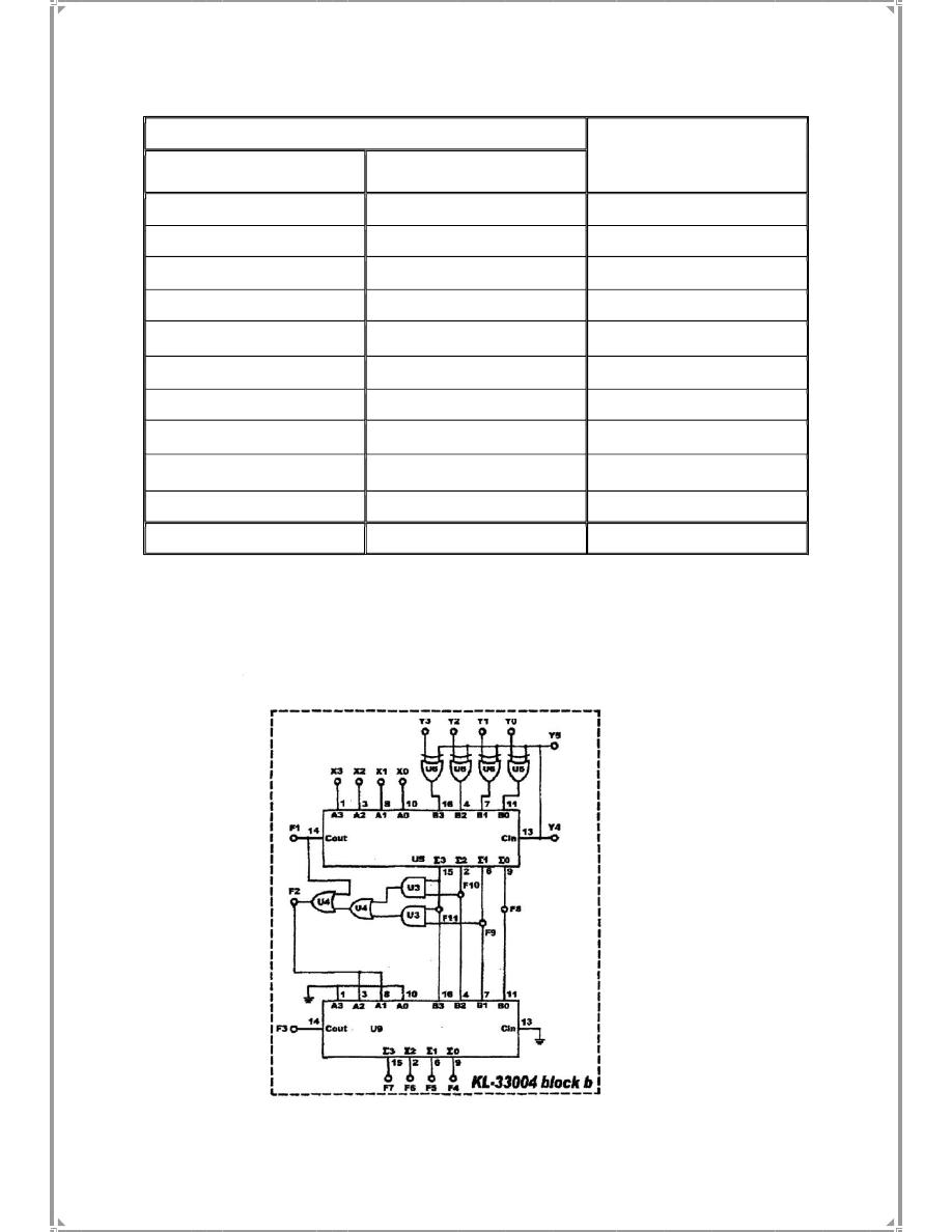
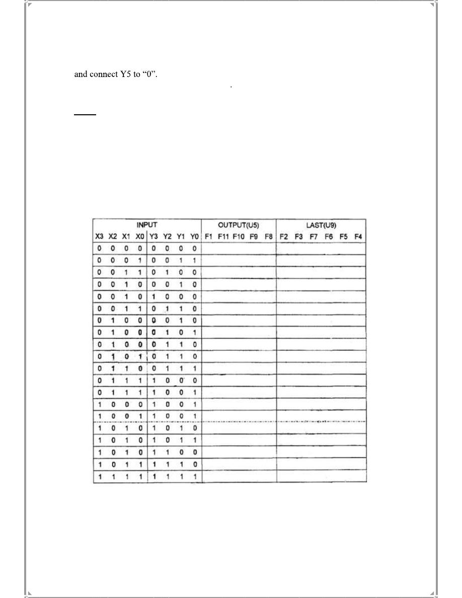
C. BCD Adder Circuit
1. The circuit shown in Fig.(3-3) below will act as a BCD code adder.
Fig.
3
-3
,
DP2.3)
(DP2.0
DIP2
to
3
Y
-
0
,Y
DP1.3)
(DP1.0
to
DIP1
3
X
-
0
Connect
inputs
X
2.
Note:
before
connecting
the
output
of
the
BCD
to
the
7-segment
decoder,
check
which
of
these
inputs
(A,
B,
C,
D)
is
the
LSB.
3
.
U
5
and
U
9
are
7483
look-ahead
4-bit
BCD
adders;
Connect
outputs
(F7-F
4
)
of
U
9
to
the
inputs
of
one
of
the
7-Segment
Digital
Display
.
Connect
F3
to
the
LSB
of
another
7-
Segment
Digital
Display.
Also ,
connect
(
F
8
- F
11)
should
to
L
0
- L
3
.
Then,
connect
F
1
to
L4,
F
2
to
L
5.
4.
Follow
the
input
sequences
for
X0 -
X3
and
Y0-Y3
in
table
(3-3)
and
record
the
output
states.
Table
(3-3)

DISCUSSIONS:
1. Pick five random
cases
from
table
(3-3)
and
discuss
their
outputs
briefly.
2. What is the
correct
compensation
when
binary
adding
is
converted
to
BCD
code?
a. Add six
b
. Subtract six
c
. Subtract nine
3
.Which
method
of
complement
should
be
used
so
that
the
result
of
A-B
=
A+B.
a.
1
,
s
complement
of
B.
b.
2
,
s
complement
of
A.
c.
2
,
s
complement
of
B.
4.
If
a
half
-
adder
circuit
is
to
be
used
as
a
half
Subtractor
circuit .
A
is
the
minuend
and
B
is
the
subtrahend
,which
of
the
following
statements
is
true?
a.
A
must
be
reversed
b.
B
must
be
reversed
c. No
modification
required
5. What
logic
gates
do
we
get
when
the
control
input
(M)
is
Set/Reset.
Explain
with
aid
of
the
truth
table.
6.
Derive
the
function
of
the
BCD
adder
(F2) using K-map.