2
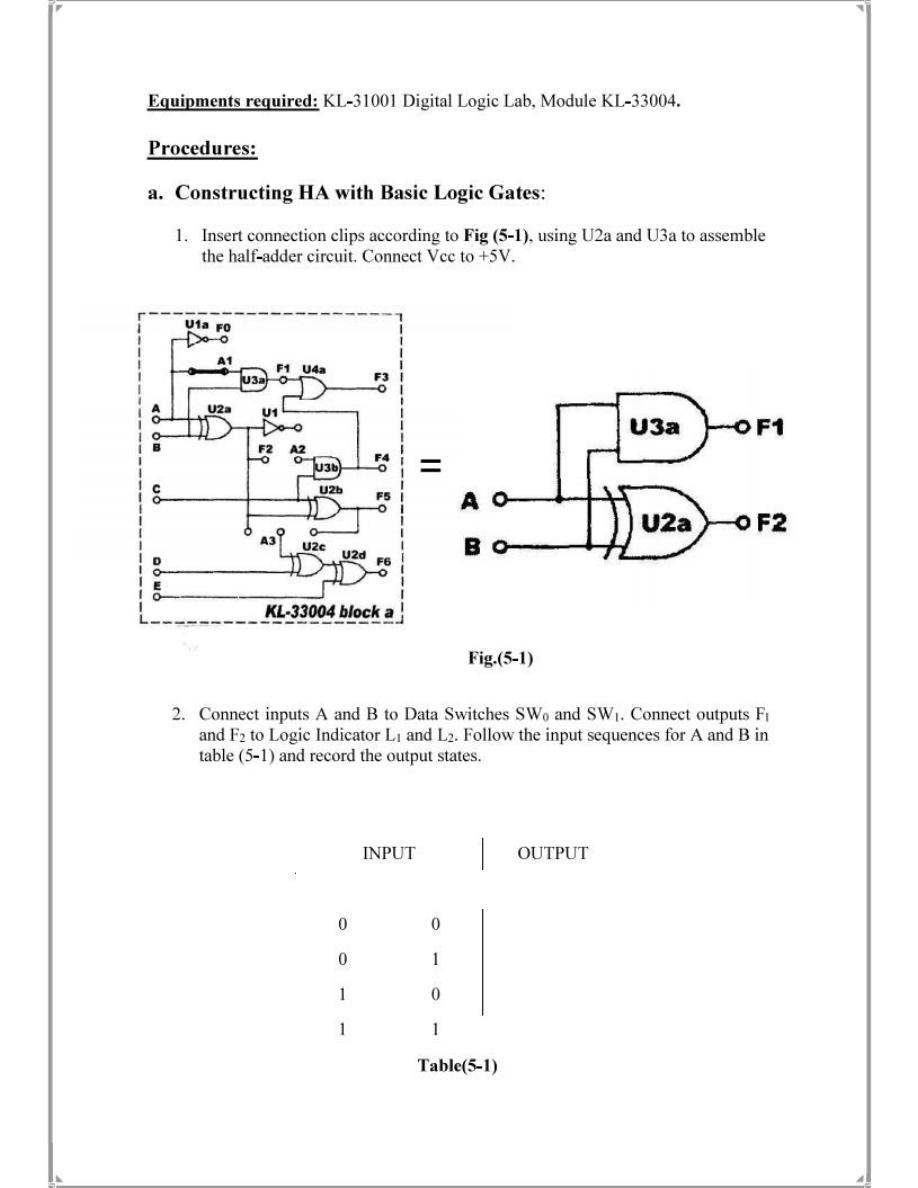
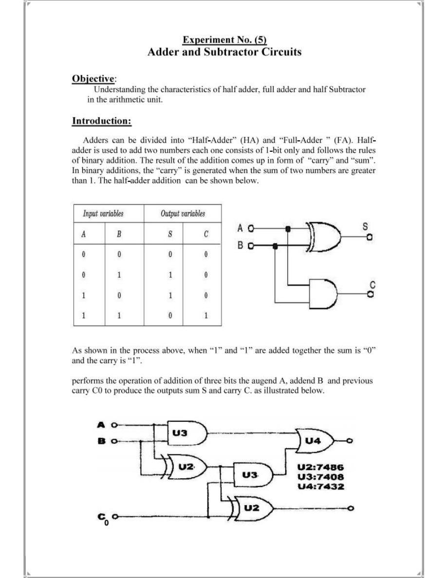
SW1(A) SW0(B) F2(S) F1(C)
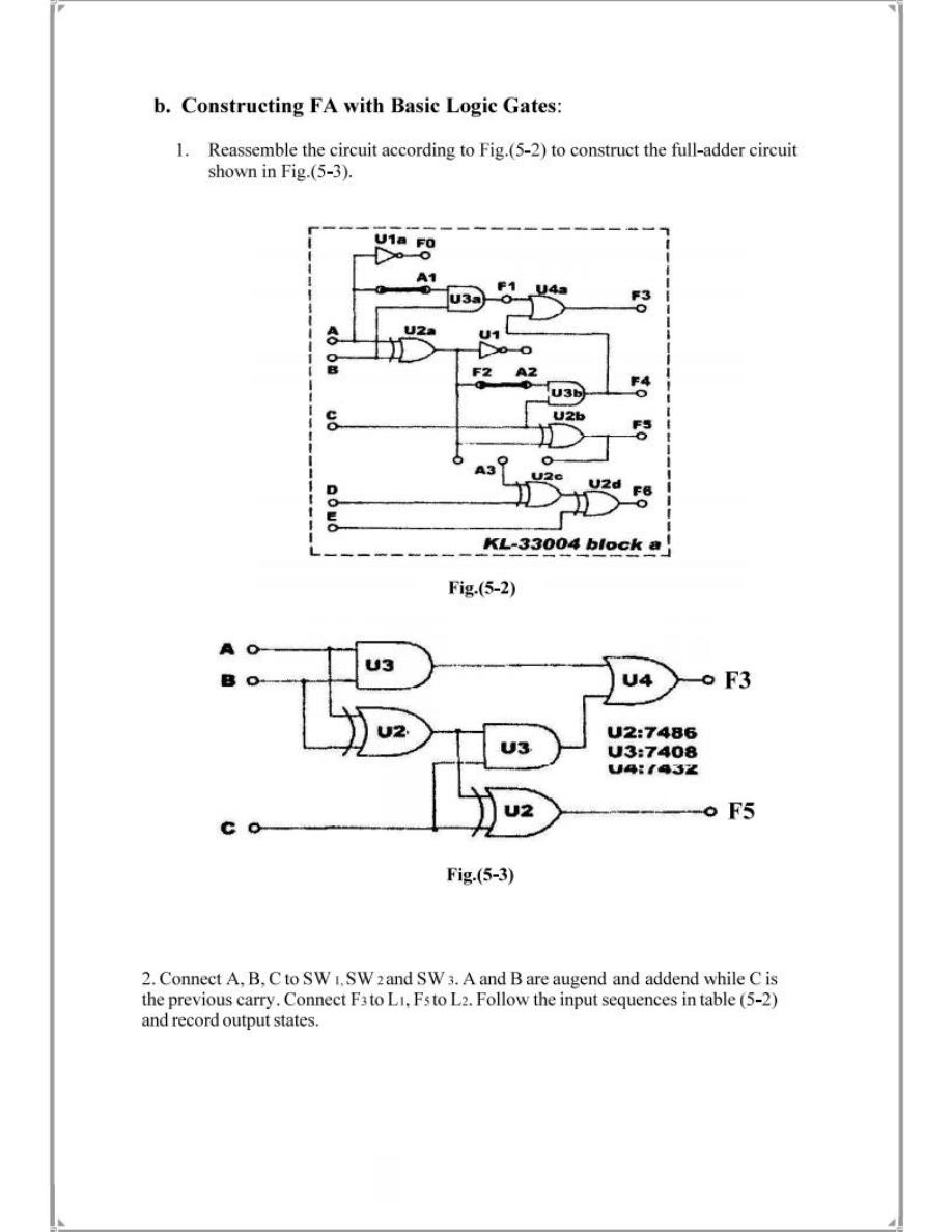
SW2(A) SW1(B) SW0(C) F5(S) F3(C)
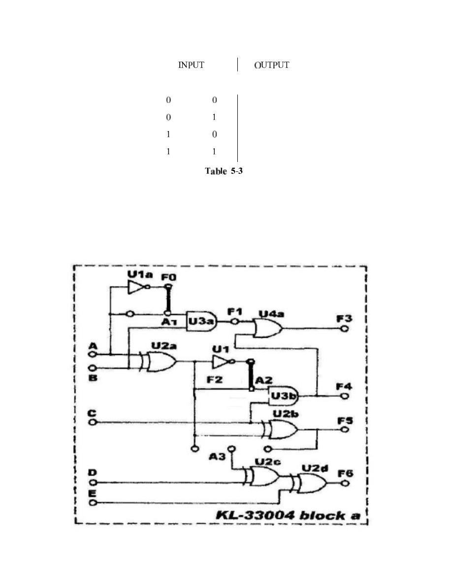
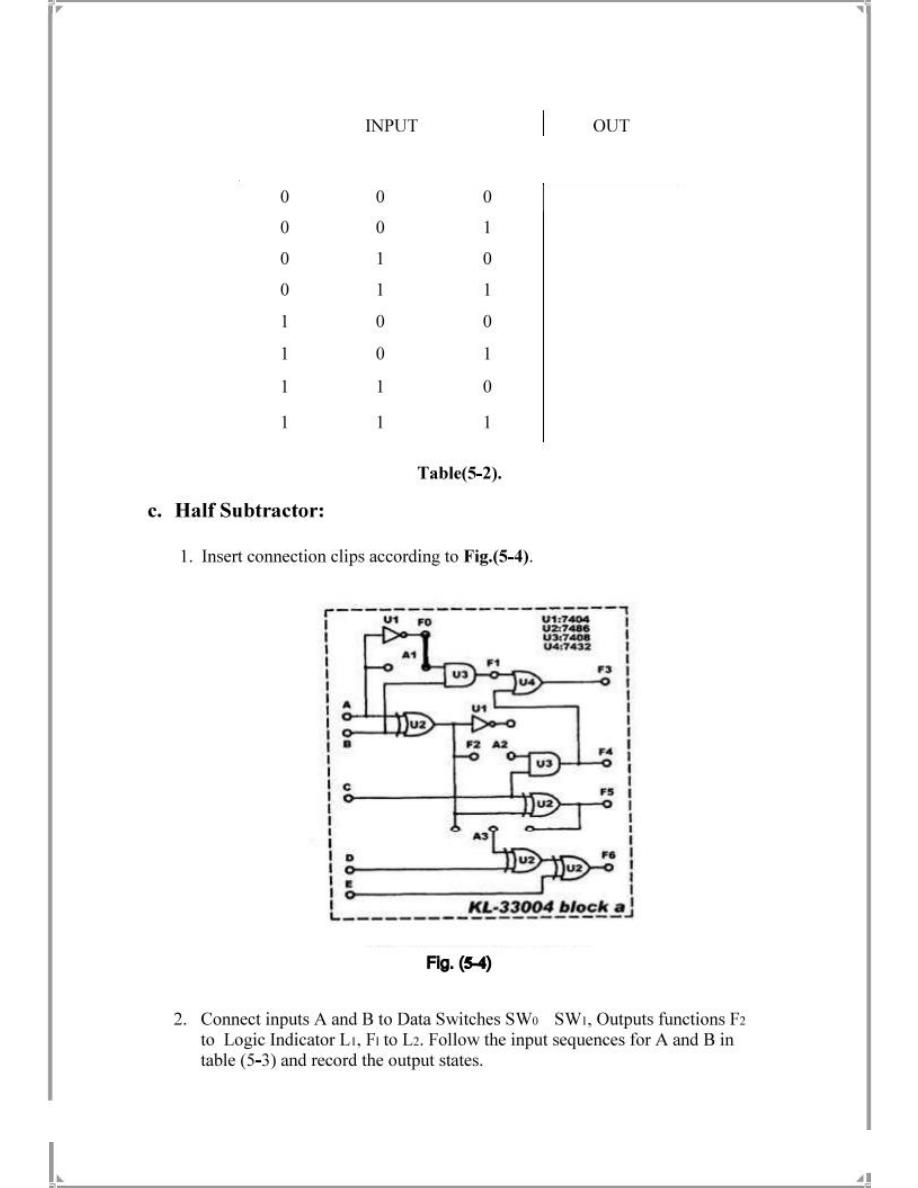
d. Constructing FS Using Logic Gates
Resemble the circuit according to figure 5-5 below to construct a full Subtractor circuit
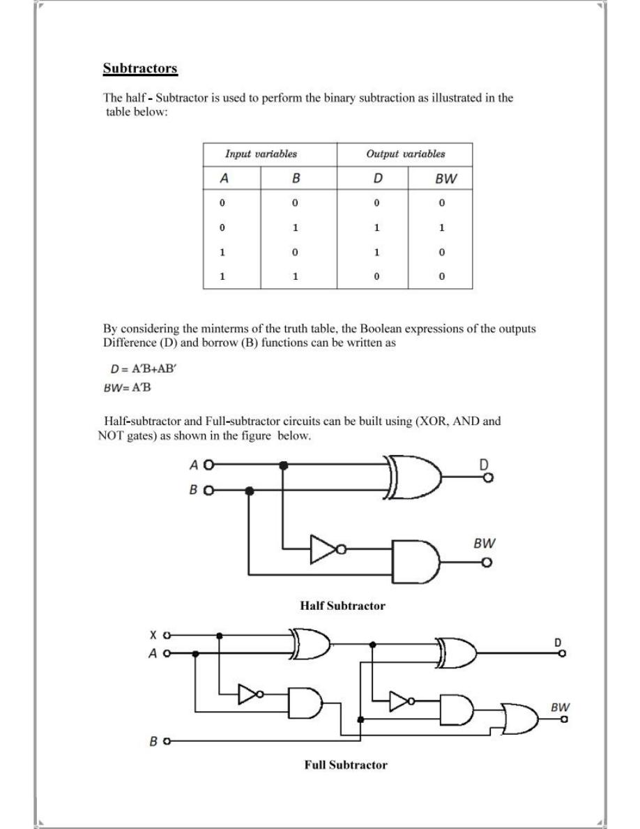
SW1(A) SW0(B) F2(D) F1(BW)

Connect A, B, C to switches SW1, SW2, SW3. A & B are Minuend and Subtrahend while C is the
previous Borrow. Connect F3 to L1, F5 to L2. Follow the input sequence in the table below to
record the output.
SW2(A) SW1(B) SW0(C) F5(D) F3(BW)