University of Ninevah
22/02/2019
Introduction to
AutoCAD
Lecture 1
By
Yazen H Shakir
& Muhannad AL-Rekany
22/02/2019
1
Why AutoCAD
Field Engineers need to deal with precise and accurate product dimensions , modern
architectures rely a lot on the curves design , electrical and control engineers
requires a tool to facilitate their wire wrapping maps ( DCS Systems).
Autodesk offers a great CAD tool launched in 1982 called AutoCAD that serves all
kind of engineers to deliver accurate production in a short time.
Thus, bridging the gap between imagination and implementation is the main
purpose behind AutoCAD where the design can be modified and optimized in an
electronic form before manufacturing it.
22/02/2019
2
University of Ninevah
22/02/2019
Benefits of CAD:
Improved productivity in Drafting
Short time for preparation
Manpower less than the one in Manual drafting
Modification is much easier
Environmentally friendly process
More accurate
Revisions many time are possible
Different colours
Assembly /De assembly drawing
Thousands of electrical, Hydraulic symbols can be stored and used inside CAD systems.
Variation of viewing ( Isometric , Projections ) in effective manner
22/02/2019
3
Limitation of CAD (AutoCAD):
Require large amount of computer memory
The license cost is considered high
The user should learn drafting principles before practicing AutoCAD
CAD Software Kinds:
AutoCAD (the one we are going to deal with during the semester)
Pro-Engineer (PTC Creo, formerly known as Pro/ENGINEER, is a 3D
CAD/CAM/CAE feature-based, associative solid modelling software)
Solidworks (specialized for 3D as well with simulation and can be connected with
3D printer) ….etc.
22/02/2019
4
University of Ninevah
22/02/2019
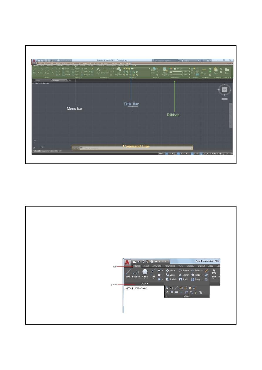
1-AutoCAD Screen:
22/02/2019
5
Title Bar
Menu bar
Ribbon
Command Line
Work Space
22/02/2019
6
1-1 Title bar:
That includes name of the opening file and in some version appears
the name of AutoCAD with its version
.
1-2 Menus bar:
This bar includes the commands of opening, closing files...etc.
(file- edit-view)
1-3 Ribbon Tabs and Panels:
The ribbon is composed of a series of tabs,
which are organized into panels that contain many of the tools and controls available
in toolbars.
University of Ninevah
22/02/2019
1-4 Command line:
In this space we can type any command you want instead of
using either the menus or the tool box as shown in the following example where
typing line command to draw a line
.
CTRL+9 to close and return the command line.
1-6 Status Bar:
The status bar displays the cursor location, drawing tools, and
tools that affect your drawing environment. The status bar provides quick access to
some of the most commonly used drawing tools. You can toggle settings such as
grid, snap, polar tracking, and object snap.
22/02/2019
7
You can also toggle some of these settings with the function keys on your keyboard
(F1 - F12).
1-7 Work Space:
It is normally black in terms of colour but we can change the
colour if required. This area can insert the drawing within its borders.
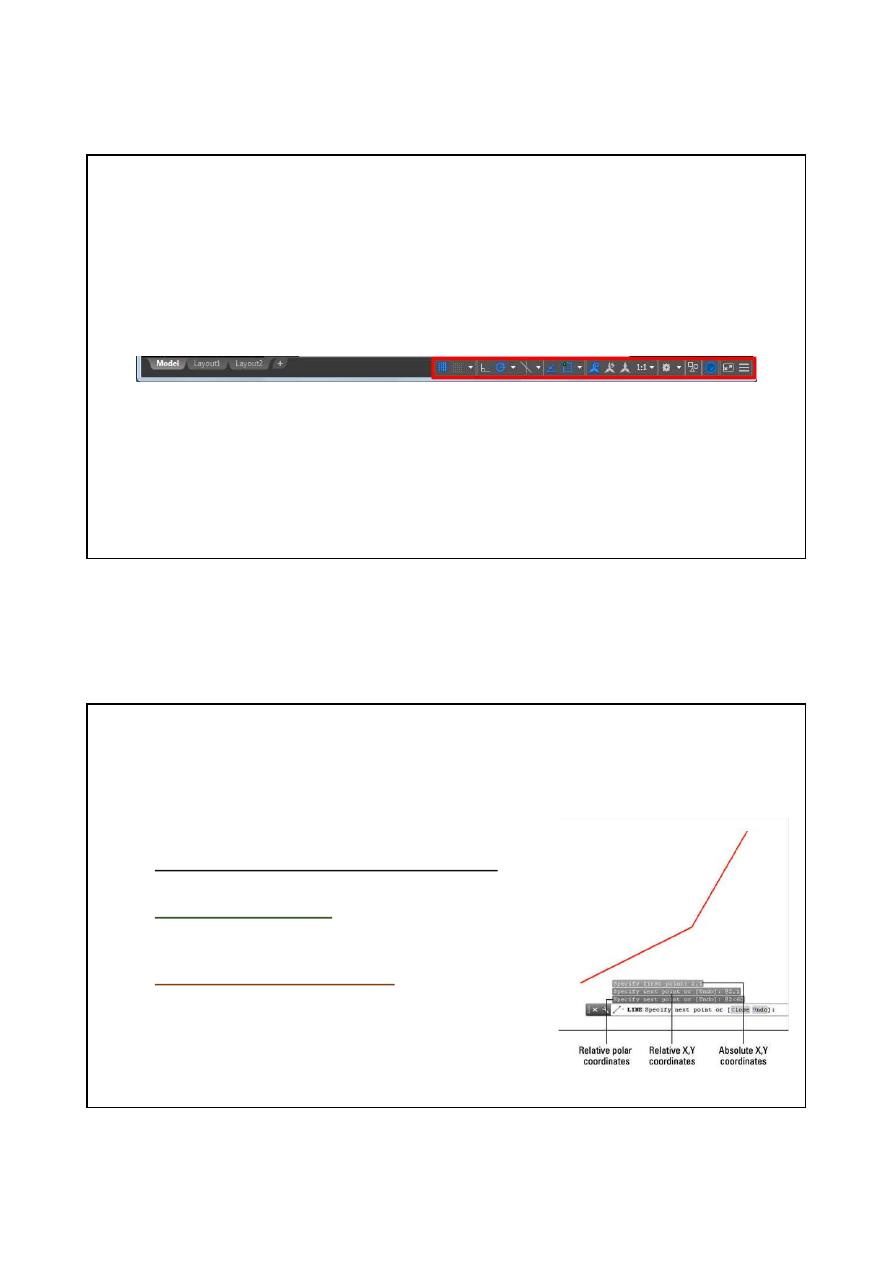
2- Coordinate System In AutoCAD
The most direct way to enter points precisely is to type
numbers with the keyboard. AutoCAD uses these keyboard
coordinate entry formats:
Absolute Cartesian (X,Y) coordinates in the
form X,Y (for example, 7,4)
Relative X,Y coordinates in the form @X,Y (for example,
@3,2): Defines a new point that is X units horizontally and
Y units vertically away from the current point.
Relative
polar
coordinates
in
the
form
@distance<angle (for example, @6<45): Defines a new
point that is the specified distance units away from the
current point at the specified angle from the origin.
22/02/2019
8
University of Ninevah
22/02/2019
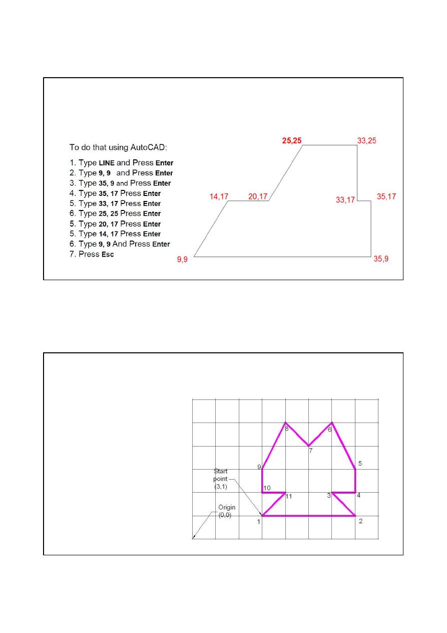
Exercise 1
22/02/2019
9
The purpose behind this task is to understand the concept of coordinates in AutoCAD. On this
project you will have to replicate the following image using the points of coordinate
annotated on the figure below
.
22/02/2019
10
Exercise 2:
Use Relative rectangular coordinates to draw the
following