Digital Techniques Lab
Experiment one
Nineveh University
College: Electronics Eng.
Dept.: Systems & Control Eng.
Digital Logic Lab KL-300
The KL-300 Digital Logic Lab is a self-contained system suitable for everyone engaged in digital
logic experiments. All necessary equipment for digital logic experiments such as power
supplies, signal generators, switches and displays are installed on the main unit KL 31001.
Specifications:
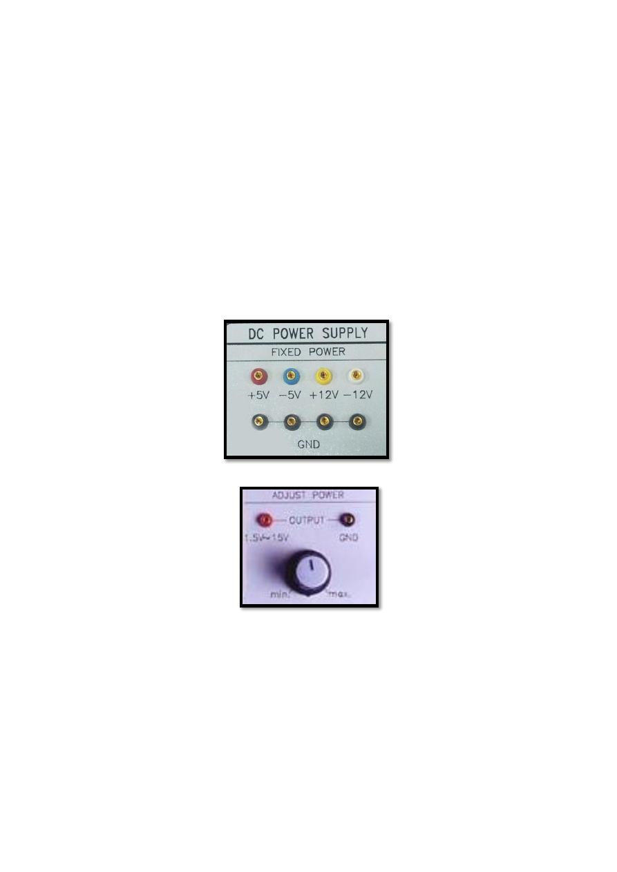
Power Supply
1. Fixed Power
Range: +5V/1.5A; -5V/0.3A; ±12V/0.3A
2. Adjustable Power
(1) Range: +1.5V →+15V
(2) Maximum Output Current: 0.5A
Signal Generators
All signal generators have TTL and CMOS level output terminal. TTL has a fixed 5V output while
CMOS level output range from +1.5V to +15V.
1. Standard Frequency
Frequency: 1MHz, 50/60HZ, 1Hz
2. Clock Generator
Six Ranges, 1Hz
– 1MHz, Continuously Adjustable.
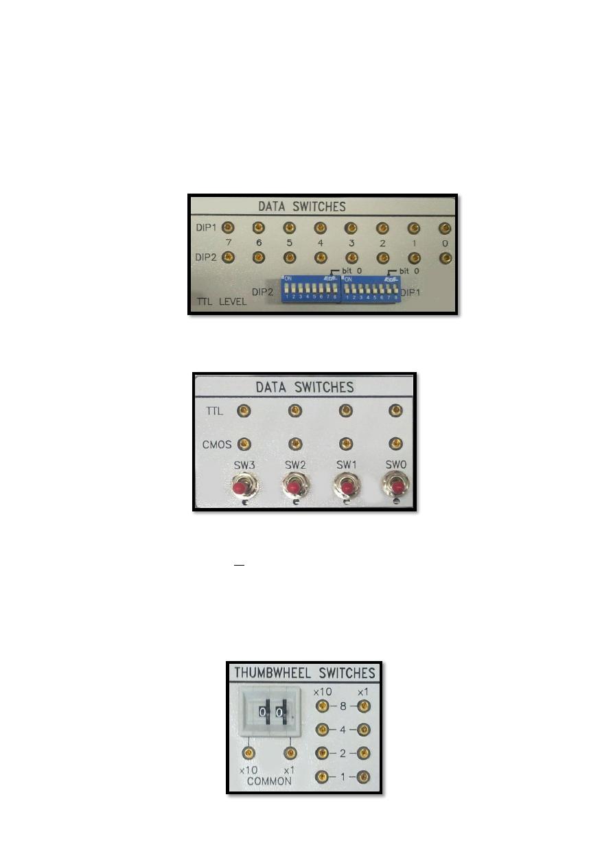
Data Switches
1. Two 8-bit DIP switches.
2. Four toggle switches.
Pulse Switches
Two toggle switches with Q and Q
Thumbwheel Switches
Two digits BCD output
Line Signal
Frequency: 50/60 Hz
Output Voltage: 6V r.m.s
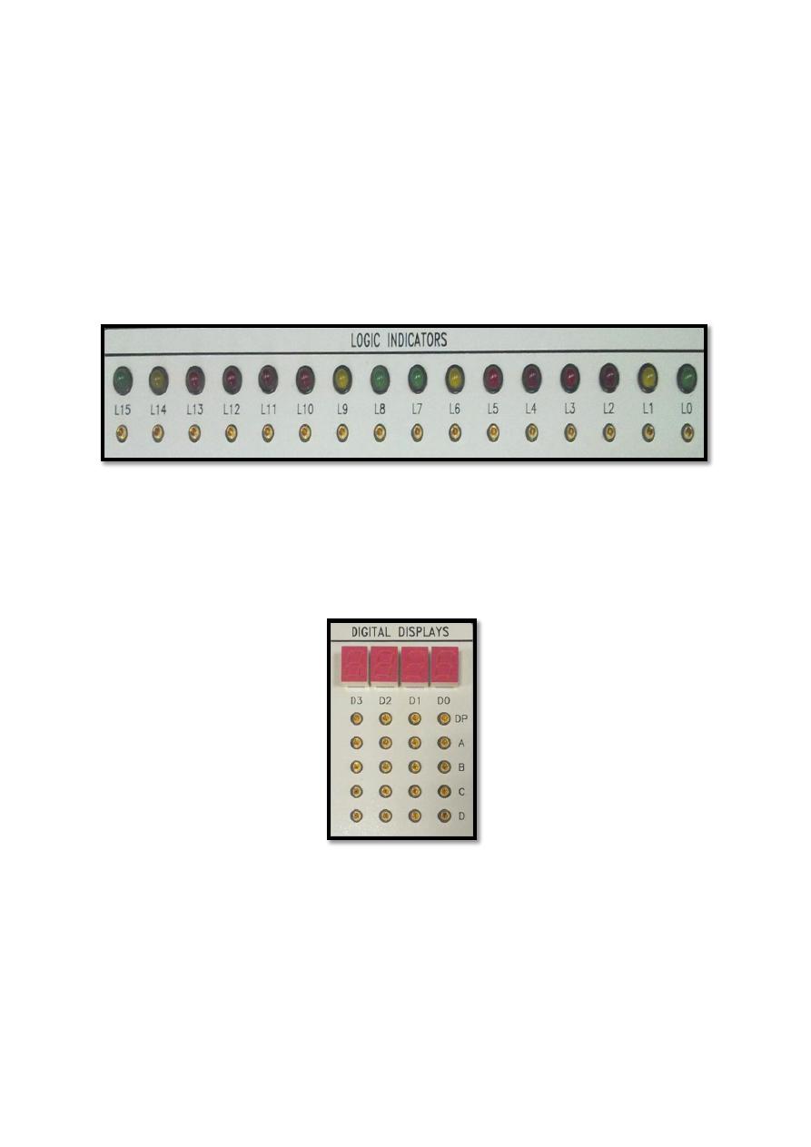
Logic Indicators
16 independent LED for "Hi-Low" logic state indication
Digital Displays
4 independent 7-segment LED displays Input with 8 • 4 • 2 • 1 BCD code.
A, B, C and D are the Input terminals. Note that all terminals use TTL signals as input voltages.
Experimental Procedure
1. Connect DIP switch first then data switch terminal to a Logic indicator and change/monitor
the switch state.
2. Connect a pulse switch terminal to a Logic indicator then change and monitor the switch
state.
3. Connect a Multimeter to a TTL toggle switch and measure the output voltage.
4. Connect a Multimeter to a CMOS toggle switch and measure the output voltage.
5. Connect the TTL input switches (SW3, SW2, SW1 and SW0) to LEDS (L3, L2, L1 and L0) then,
change the input from (0000 to 1111) and show the outputs on the LEDS.
6. Connect the DIP1 input switches (0 to 7) to the output LEDS (L0 to L7) then display the
following values in binary (9, 33, 69, 106, 250).
7. Connect toggle Switch to a digital display then change the input and record the output
according to the table below:
D
C
B
A
DISPLAY
D
C
B
A
DISPLAY
0
0
0
0
1
0
0
0
0
0
0
1
1
0
0
1
0
0
1
0
1
0
1
0
0
0
1
1
1
0
1
1
0
1
0
0
1
1
0
0
0
1
0
1
1
1
0
1
0
1
1
0
1
1
1
0
0
1
1
1
1
1
1
1
8. Connect the thumbwheel switches common inputs (x1 and x10) to the power supply (+5V).
connect the output of x1 to the 7-segment digital display D0 and to LEDs (L0, L1, L2 and L3).
Also connect the output of x10 to the 7-segment digital display D1 and to LEDs (L4, L5, L6
and L7). Now change the input form (00 to 25) and show the results on 7-segments and
LEDS at the same time.
Questions
Q1) What is TTL and CMOS voltage level?
Q2) How could you change the CMOS output level?
Q3) What is the difference between CMOS and TTL circuits?
Q4) How do the
Digits 10-14 are displayed
on the digital display?
Q5) What happens if you connect a CMOS input signal to the digital display?