Principles of MRI magnetic resonance imaging
Dr Mohammed Bader HassanFIBMS,DMRD
Objectives
By the end of this lecture the student should be able to1.calrify the basics of MRI physics
2.define major MRI sequences (T1&T2)
3.identify the MRI advantages and contraindications
4.identify the major MRI studies such is angiography, MRCP and myelography
Basic facts
the human contain a predominant of hydrogen atoms (in water ,fat ,and other tissues)The hydrogen atom contain a proton only
The proton is a particle with a positive charge
Each proton have a spin movement
The moving charge is electrical current which have magnetic field
So each proton have own magnetic field
P
=
No Net
Magnetization
What happen when the body inside the magnetic field
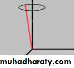
1.the proton (small magnets )organize the selves with the external magnets2.a precession movement begin (just like when you hit the top of spin )it is a wobble movement
This precession have the specific frequency according to type of atom and magnetic field (so it is a well known frequency)

how can we get a picture from MRI
It is difficult to measured aligned magnets inside a river of magnetic field so we should shift this magnetic fieldWe send a radio wave in the same frequency of the precession of the proton (radio frequency )resonance!
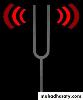
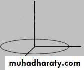
Measuring Tissue Magnetization:
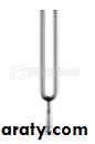
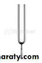
For an energy transfer to occur the RF Pulse must be at the samefrequency as the precessing Mo. ie The Resonance Frequency.
Much like a tuning fork experiment.
B
A
B
C
D
E
Measuring Tissue Magnetization:
BA
B
C
D
E
Measuring Tissue Magnetization:
AB
C
D
E
B

Measuring Tissue Magnetization:
AB
C
D
E
B
Measuring Tissue Magnetization:
AB
C
D
E
B
What happen after radiofrequency is sent
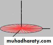
The radio frequency should be in the same frequency of the precession of proton so it can transfer energy to protonThe energy which is picked up by proton will make the proton in higher energy this will make the longitudinal magnetic vector of the body is zero
And it will synchronized the precession of the protons which will move in the same direction & will give moving transverse vector
Moving transverse vector
What happen after the radiofrequency is off
The energy will be loosed from the spinning proton and longitudinal vector appear again in a specific time according to tissue component.The synchronization (the transvers vector will be loosed in specific time according to tissue component
T1 Relaxation
T1 Relaxation
x'y'
z'
T1 relaxation is regrowth of the longitudinal magnetization
T1=the time which is needed for most of the longitudinal vectored to re appearT1 Relaxation
x'y'
z'
T1 relaxation is regrowth of the longitudinal magnetization
T1 Relaxationx'
y'
z'
T1 relaxation is regrowth of the longitudinal magnetization
T1 Relaxationx'
y'
z'
T1 relaxation is regrowth of the longitudinal magnetization
T1 Relaxationx'
y'
z'
Mlong = M0
T1 relaxation is regrowth of the longitudinal magnetizationT2 Decay
x'
y'
z'
T2 relaxation is dephasing of transverse magnetization
x'y'
z'
-
-
-
+
+
+

The time which is needed to disappear of most of the transverse vectored is T2
Decay of transvers vectoreT2
Transverse vector
MR SIGNAL
Collected by a coilEncoded through a series of complex techniques and calculations (magic?)
Stored as data
Mapped onto an image matrix
T1 Relaxation:
With no other signal considerationsthis would mean that the protons
with short T1 time would
contribute the highest signal
on the image.
Pixel containing protons
with short T1 time.
(eg Fat)
With no other signal considerations
this would mean that the protons
with a long T2 time would
contribute the highest signal
on the image.
Pixel containing protons
with long T2 time.
(eg Water)
T2 Decay:
TR - REPETITION TIMETime from the application of one RF pulse to another RF pulse
TE - ECHO TIMETime from the application of the RF pulse to the peak of the signal induced in the coil
Image formationThe image will depend on T1,T2, and amount of proton within the tissue (spin density ) .
The fatty tissues is loosing energy quickly so it will re appear its longitudinal vector rapidly ( high T1 signal)
Fatty tissue will loss synchronization quickly
Water loosing energy and synchronization slowly so it will appear bright at T2 and black on T1
Solid material will not give a signal on t1 and t2 (signal void )
air will appears signal void because lack of H .
T1 WEIGHTING
A short TR and short TE will result in a T1 weighted imageExcellent for demonstrating anatomy
T2 WEIGHTING
A long TR and long TE will result in a T2 weighted image
Excellent for demonstrating pathologyMANY OTHER DIFFERENT TYPES OF IMAGES THAT COMBINE ABOVE AND INCLUDE OTHER PARAMETERS
Relative Relaxation Rates• T1
• T2
• Time
• Color in image• Time
• Color in image
• Solid (bone ,stone )
• Long
• black
• short
• Black
• semi-solid (muscle )
• intermediate
• intermediate
• intermediate
• intermediate
• liquid
• long
• dark
• long
• bright
• Fat
• short
• bright
• short
• Dark
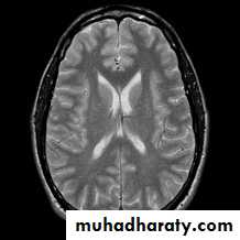
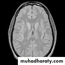
T1-, -, and T2-weighted images
-weightedT2-weighted
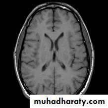
T1-weighted
Brain Tumor Imaging
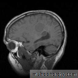
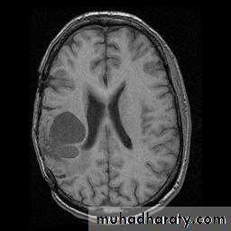
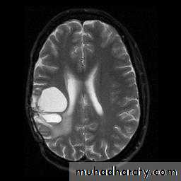
What’s changed between these images?
T1-weighted Sagittal
T1-weighted Axial
T2-weighted Axial
STIR = Short Tau Inversion
RecoveryFAT
STIR = Short Tau Inversion
RecoveryFAT
STIR = Short Tau Inversion
RecoveryFAT
STIR = Short Tau Inversion
RecoveryFAT
STIR = Short Tau Inversion
RecoveryFAT
STIR = Short Tau Inversion
RecoveryFAT
Very Small transverse component = small signal
90 deg
STIR = Short Tau Inversion
RecoveryFat & water
STIR = Short Tau InversionRecovery
Fat & water
STIR = Short Tau Inversion
RecoveryFat & water
STIR = Short Tau InversionRecovery
Fat & water
STIR = Short Tau InversionRecovery
Fat & water
STIR = Short Tau InversionRecovery
Water will have signal. Fat will not!
Fat & water90 deg
Advantage of MRI
Non ionizing radiation
Multiplanar images (cross section , saggital and coronal views )
The ability of imaging vessels without contrast (MR angiography )
Have a good soft tissue contrast
Contraindication of MRI
Patient with pacemakerPatient with bullet injury or ferromagnetic F.B ,or surgical clip (because of heat and missile effect )
Pregnancy especially first trimester
Claustrophobia reported that between 1 % and 10 % of patients experience some degree of claustrophobia which in the extreme cases results in their refusal to proceed with the scan
bioeffect
No known or expected harmful effects on humans using field strengths up to 10 TeslaCurrently pregnant women are normally excluded from MRI scans during the first trimester although there is no direct evidence to support this restriction
The most invasive MR scans involve the injection of contrast agents (e.g. Gd-DTPA).
noise

DISADVANTAGES OF MRI
Expensive
Long scan times
Audible noise (65-115dB)
Isolation of patient (claustrophobia, monitoring of ill patients)
Exclusion of patients with pacemakers and certain implants
Monitoring equipment
Infusion pumpsCredit cards
Cellular telephones
Any electronic device
THE CHANGING MAGNETIC FIELDS CAN DO DAMAGE TO:
Gold
SilverDigital watches
Eyeglass frames
Snaps/zippers fastened to clothing
Dental work
THE FOLLOWING ARE (USUALLY*) OKAY:
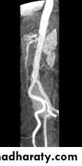
Special MRI studies
MR angiography :non-invasive imaging of the vascular tree , In normal circumstances flow effects cause unwanted artefacts, but in MRA these phenomemna are used advantageously ,
Direction of
Blood Flow.Direction of
Blood Flow.Direction of
Blood Flow.Direction of
Blood Flow.Direction of
Blood Flow.Overall signal
from Voxel isreduced due to
Phase Loss.
Vascular Techniques
2D ToF
Blood flowing into
the slice is fully magnetized
so when it receives an
RF pulse it is flipped
into the transverse
plane and gives
a high signal.
Arrows represent
Mo VectorVascular Techniques
2D ToFStationary tissue receives
continual RF pulses that
arrive before the proton
can relax back to Bo.
This causes
Saturation of the
stationary tissue
and therefore less signal
from the stationary tissue.
2D ToF sequences
utilize short TR’s and
high flip angles.
Eg: 33ms & 70deg.
Vascular Techniques
2D ToF
Blood flowing into
the slice is fully magnetized
so when it receives an
RF pulse it is flipped
into the transverse
plane and gives
a high signal.
Venous Flow
DirectionArrows represent
Mo VectorVenous Flow
DirectionBy placing an
additional 90degRF pulse in the
path of the venous
blood we can
saturate its signal
before it enters the
imaging slice.
This is referred to
as a Pre-Saturation
Pulse.
Vascular Techniques
2D ToF
The resultant image shows
flowing blood with
bright signal and the
stationary tissue
as a “saturated”
signal.
The venous blood is saturated
in the same manner as stationary
tissue and contributes no signal.
2D ToF
By acquiring manyindividual slices long
vessels may be covered
easily. The resulting slices
are then combined and
viewed as a maximum
intensity projection (MIP)
in any orientation.
Vascular Techniques
Vascular Techniques
2D ToFThe resultant image
may be rotated, paged
and manipulated to
demonstrate the
optimum viewing
plane.
(With IVI or AW
software packages)
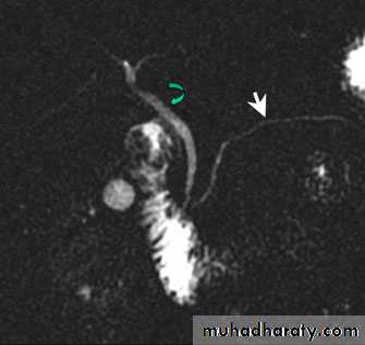
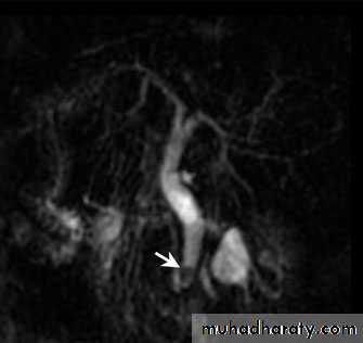
MRCP
Magnetic resonance colangio pancreaticography:Heavily T2 weighted imaged for biliarry and pancreatic tree
No need for contrast
No need for endoscopy
Non invasive method
Normal duct stone
MR mylogarphy
Heavily T2 weighted image ,used for imaging spinal canal and theca sac , with out the need for injection of contrast in the thecal sac ( non invasive method )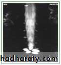
QUESTIONS?????

Thank you