Intraoral Radiography
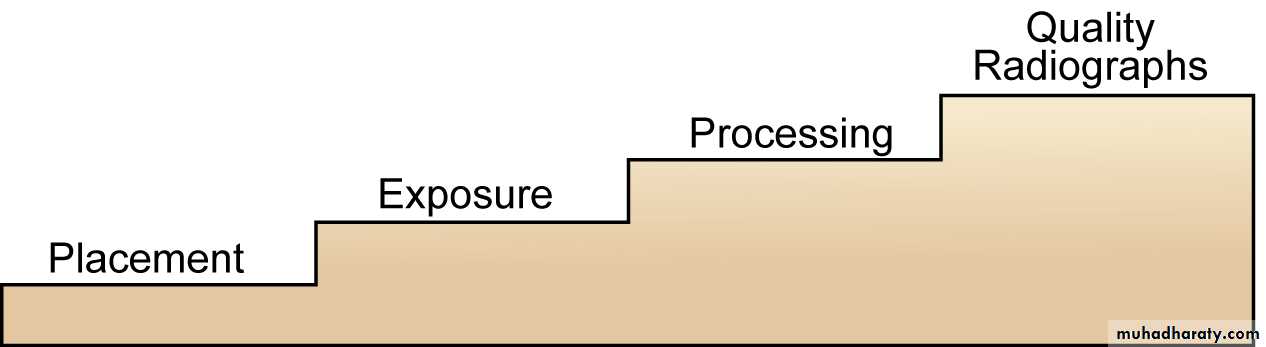
Radiographs should be free from distortion, have the correct density and contrast, and can be used for the detection of dental disease.To produce quality dental radiographs the following steps should be done carefully: Film Placement, Exposure, and Processing.
Types of Intraoral Radiography:
Shadow Casting Principles
• The source of radiation should be as small as possible.• The distance from the radiation source to the object should be as long as possible.
• The distance from the object to the image receptor should be as short as possible.
• The object & the image receptor should be parallel.
• The primary x-ray beam should be perpendicular to both object & image receptor.
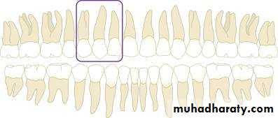
Periapical Examination
Main Indications:Detection of apical lesions.
Assessment of the periodontal status.
After trauma to the teeth and associated alveolar bone.
Assessment of the unerupted teeth.
Assessment of root morphology before extractions.
During endodontics.
Preoperative assessment and postoperative appraisal of apical surgery.
Evaluation of implants postoperatively.
There are two basic techniques for obtaining periapical radiographs:
Bisecting angle technique.Paralleling technique.
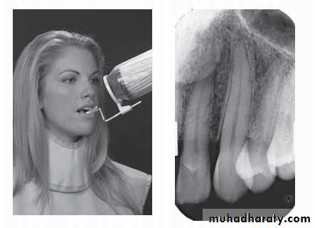
PID Angulations: Bisecting Technique
Angulation is a term used to describe the alignment of the central ray of the x-ray beam in the horizontal and vertical planes.
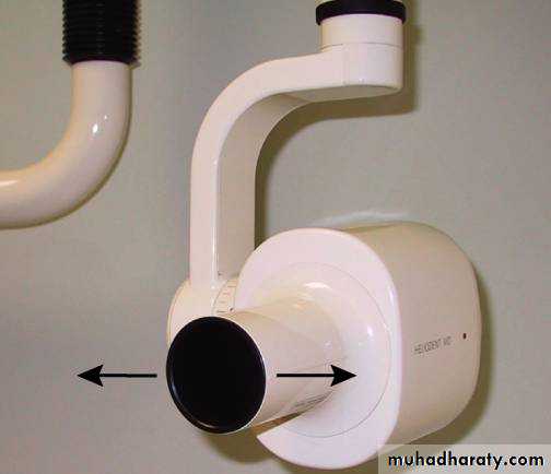
Angulation can be changed by moving the PID in either a horizontal or vertical direction.
Horizontal angulation refers to the positioning of the tube head and direction of the central ray in a horizontal.
The horizontal angulation remains
the same whether you are using the
paralleling or bisecting technique.
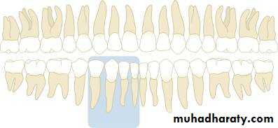
With correct horizontal angulation, the central ray is directed perpendicular to the curvature of the arch and through the contact areas of the teeth.
Incorrect horizontal angulation results in overlapped contact areas.

Vertical angulation refers to the positioning of the PID in a vertical, or up-and-down, plane.
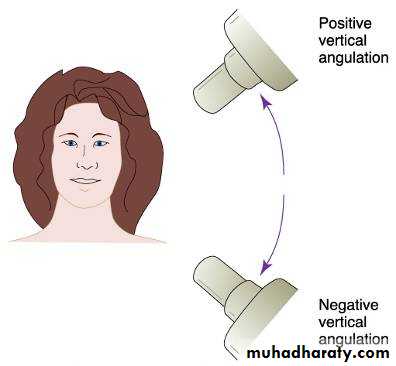

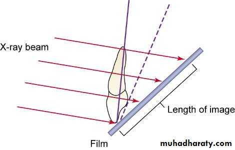
Correct vertical angulation results in a radiographic image that is the same length as the tooth.
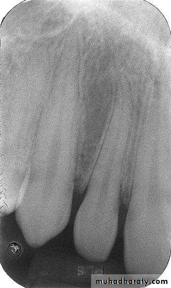
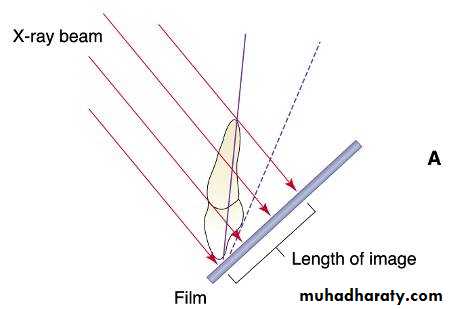
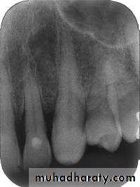
Incorrect vertical angulation results in:
The image appears either longer(Elongated),or shorter(Foreshortened).


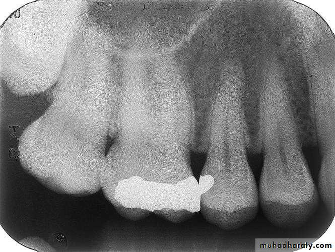
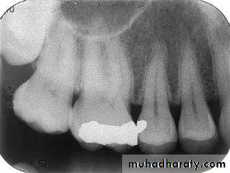
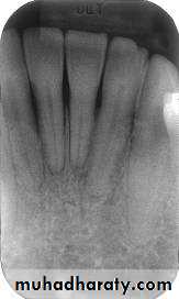
This radiograph demonstrates a cone cut.

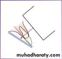
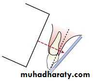
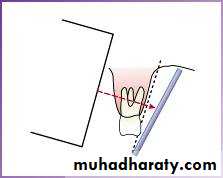
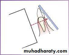
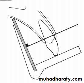
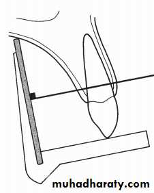
The Bisecting Technique
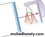
The angle formed by the long axis of the teeth and the film is bisected, and the x-ray beam is directed perpendicular to the bisecting line.
Maxillary incisor exposure


+40°
Maxillary canine exposure

+45°
Maxillary premolar exposure
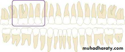


+30°
Maxillary molar exposure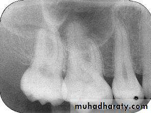
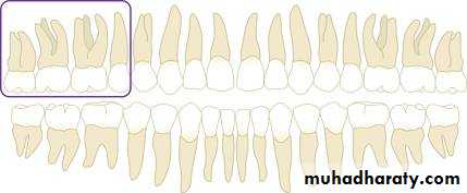

+20°
Mandibular incisor exposure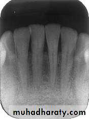

-15°
Mandibular canine exposure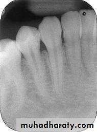

-20°
Mandibular premolar exposure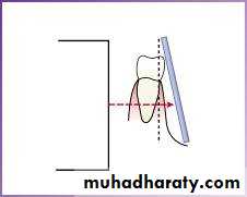
-10°
Mandibular molar exposure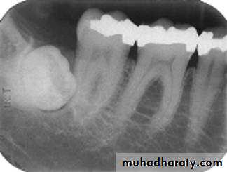


-5°
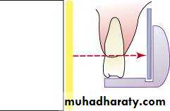
Paralleling Technique• The film is placed in a holder and positioned in the mouth parallel to the long axis of the tooth under investigation (magnification) target-film distance
• long PID.
2. The X-ray tube head is then aimed at right angles (vertically and horizontally) to both the tooth and the film .
3. A film holder must be used to hold the film parallel with the long axis of the tooth. The patient cannot hold the film. The technique is reproducible.
This positioning has the potential to satisfy four of the five ideal requirements of shadow cast principles.
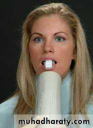
Assembling the XCP (Extension-Cone Paralleling Instruments), Anterior Assembly
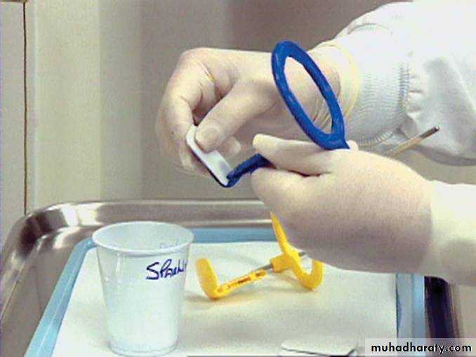
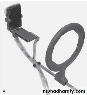
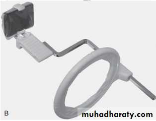
Respecter holding instrument XCP
A device used for holding the film parallel to the teeth.*A bite block or platform.
*An X-ray beam-aiming device.
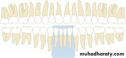
Maxillary incisor region

Maxillary canine region

Maxillary premolar region
Maxillary molar region


Mandibular incisor region


Mandibular canine region
Mandibular premolar region

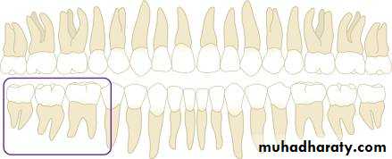
Mandibular molar region
Advantages of the Bisected Angle Technique
• Positioning of the film packet is reasonably comfortable for the patient in all areas of the mouth.• Positioning is relatively simple and quick.
• If all angulations are assessed correctly, the image of the tooth will be the same length as the tooth itself and should be adequate (but not ideal) for most diagnostic purposes.
Disadvantages of the Bisected Angle Technique
The many variables involved in the technique often result in the image being badly distorted.Incorrect vertical angulation will result in foreshortening or elongation of the image.
The periodontal bone levels are poorly shown.
The shadow of the zygomatic bone frequently overlies the roots of the upper molars.
The horizontal and vertical angles have to be assessed for every patient and considerable skill is required.
It is not possible to obtain reproducible views.
Coning off or cone cutting may result if the central ray is not aimed at the centre of the film, particularly if using rectangular collimation.
Incorrect horizontal angulation will result in overlapping of the crowns and roots.
The crowns of the teeth are often distorted, thus preventing the detection of approximal caries.
The buccal roots of the maxillary premolars and molars are foreshortened.
Advantages of the Paralleling Technique
1. Geometrically accurate images are produced with little magnification.2. The shadow of the zygomatic bone appears above the apices of the molar teeth.
3. The periodontal bone levels are well represented.
4. The periapical tissues are accurately shown with minimal foreshortening or elongation.
5. The crowns of the teeth are well shown enabling the detection of proximal caries.
6. The horizontal and vertical angulations of the X-ray tube head are automatically determined by the positioning devices if placed correctly.
7. The X-ray beam is aimed accurately at the centre of the film — all areas of the film are irradiated and there is no cone cutting.
8. Reproducible radiographs are possible at different visits and with different operators.
9. The relative positions of the film packet, teeth and X-ray beam are always maintained, irrespective of the position of the patient’s head. This is useful for some patients with disabilities.
Disadvantages of the Paralleling Technique
1. Positioning of the film packet can be very uncomfortable for the patient, particularly for posterior teeth, often causing gagging.
2. Positioning the holders within the mouth can be difficult for inexperienced operators.
3. The anatomy of the mouth sometimes makes the technique impossible, e.g. a shallow, flat palate.
4. The apices of the teeth can sometimes appear very near the edge of the film.
5. Positioning the holders in the lower third molar regions can be very difficult.
6. The technique cannot be performed satisfactorily using a short focal spot to skin distance because of the resultant magnification.
7. The holders need to be autoclavable or disposable.
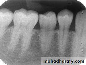
Bite-wing Radiography
• Indications:• Interproximal caries.
• Over-hang filling.
• Level of crestal bone between the teeth.
• Interproximal calculus.
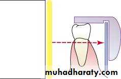
• Principles:
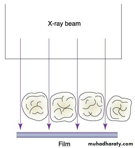
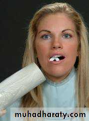
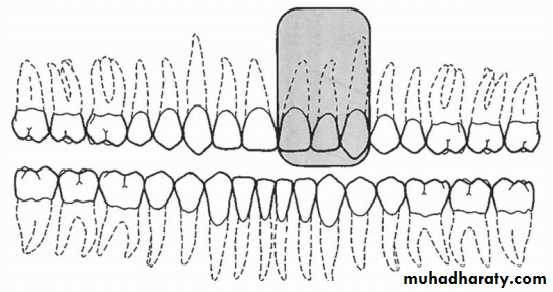
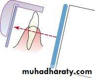
• The film is placed in the mouth parallel to the crown of both upper & lower teeth.
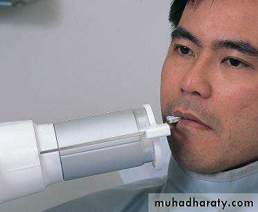
• The film stabilized when the patient bites on the bite-wing tab or bite-wing film holder.
• The central ray of the x-ray beam is directed through the contacts of the teeth, using a +10 degree vertical angulation.

+10o vertical angulation is used to compensate for the slight bend of the upper portion of the film and the tilt of the maxillary teeth.

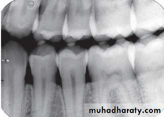
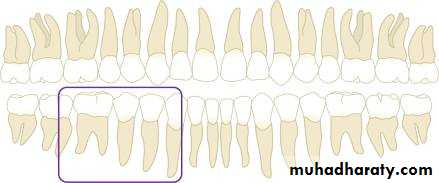
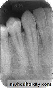
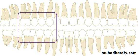
Premolar bitewing. A, Film placement. B, Resultant radiograph.
AB

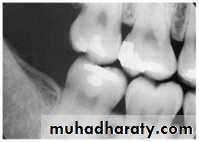
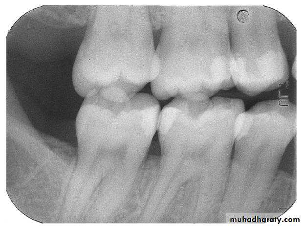
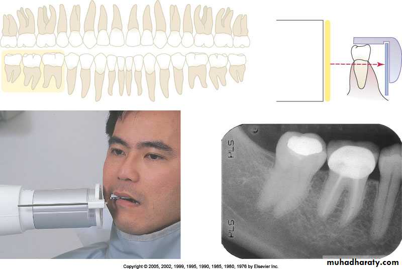
The molar-bitewing. A, Film placement. B, Resultant radiograph.
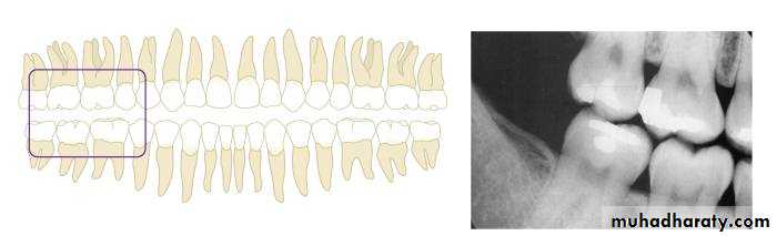
A
B