I
n radio transmission, it is necessary to send audio
signal (e.g. music, speech etc.) from a broadcasting
station over great distances to a receiver. This com-
munication of audio signal does not employ any wire and
is sometimes called
wireless.
The audio signal cannot be
sent directly over the air for appreciable distance. Even
if the audio signal is converted into electrical signal, the
latter cannot be sent very far without employing large
amount of power. The energy of a wave is directly pro-
portional to its frequency. At audio frequencies (20 Hz to
20 kHz), the signal power is quite small and radiation is
not practicable.
The radiation of electrical energy is practicable only
at high frequencies e.g. above 20 kHz. The high frequency
signals can be sent thousands of miles even with com-
paratively small power. Therefore, if audio signal is to be
16.1
Radio Broadcasting,
Transmission and Reception
16.2
Modulation
16.3
Types of Modulation
16.4
Amplitude Modulation
16.5
Modulation Factor
16.6
Analysis of Amplitude
Modulated Wave
16.7
Sideband Frequencies in
AM Wave
16.8
Transistor AM Modulator
16.9
Power in AM Wave
16.10
Limitations of Amplitude
Modulation
16.11
Frequency Modulation
16.12
Theory of Frequency
Modulation
16.13
Comparison of FM and AM
16.14
Demodulation
16.15
Essentials in Demodulation
16.16
A.M. Diode Detector
16.17
A.M. Radio Receivers
16.18
Types of A. M. Radio
Receivers
16.19
Stages of Superhetrodyne
Radio Receiver
16.20
Advantages of
Superhetrodyne Circuit
16.21
FM Receiver
16.22
Difference Between FM And
AM Receivers
INTRODUCTION
Modulation and
Demodulation
16
412
Principles of Electronics
transmitted properly, some means must be devised which will permit transmission to occur at high
frequencies while it simultaneously allows the carrying of audio signal. This is achieved by superim-
posing electrical audio signal on high frequency carrier. The resultant waves are known as
modu-
lated waves
or
radio waves
and the process is called
modulation.
At the radio receiver, the audio
signal is extracted from the modulated wave by the process called
demodulation.
The signal is then
amplified and reproduced into sound by the loudspeaker. In this chapter, we shall focus our attention
on the various aspects of modulation and demodulation.
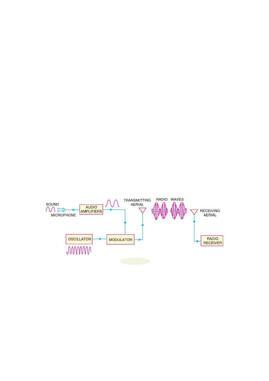
16.1 Radio Broadcasting, Transmission and Reception
Radio communication means the radiation of radio waves by the transmitting station, the propagation
of these waves through space and their reception by the radio receiver. Fig. 16.1 shows the general
principles of radio broadcasting, transmission and reception. As a matter of convenience, the entire
arrangement can be divided into three parts viz.
transmitter, transmission of radio waves
and
radio
receiver.
1. Transmitter.
Transmitter is an extremely important equipment and is housed in the broad-
casting station. Its purpose is to produce radio waves for transmission into space. The important
components of a transmitter are microphone, audio amplifiers, oscillator and modulator (See Fig. 16.1).
(i) Microphone.
A microphone is a device which converts sound waves into electrical waves.
When the speaker speaks or a musical instrument is played, the varying air pressure on the micro-
phone generates an audio electrical signal which corresponds in frequency to the original signal. The
output of microphone is fed to a multistage audio amplifier for raising the strength of weak signal.
(ii) Audio amplifier.
The audio signal from the microphone is quite weak and requires amplifi-
cation. This job is accomplished by cascaded audio amplifiers. The amplified output from the last
audio amplifier is fed to the modulator for rendering the process of modulation.
Fig. 16.1
(iii) Oscillator.
The function of oscillator is to produce a high frequency signal, called a
carrier
wave.
Usually, a crystal oscillator is used for the purpose. The power level of the carrier wave is
raised to a sufficient level by radio frequency amplifier stages (not shown in Fig. 16.1). Most of the
broadcasting stations have carrier wave power of several kilowatts. Such high power is necessary for
transmitting the signal to the required distances.
(iv) Modulator.
The amplified audio signal and carrier wave are fed to the modulator. Here, the
audio signal is superimposed on the carrier wave in a suitable manner. The resultant waves are called
modulated waves or radio waves and the process is called
modulation
. The process of modulation
permits the transmission of audio signal at the carrier frequency. As the carrier frequency is very
high, therefore, the audio signal can be transmitted to large distances. The radio waves from the
transmitter are fed to the transmitting antenna or aerial from where these are radiated into space.

Modulation And Demodulation
413
2. Transmission of radio waves.
The transmitting antenna radiates the radio waves in space
in all directions. These radio waves travel with the velocity of light i.e. 3
× 10
8
m/sec. The radio
waves are electromagnetic waves and possess the same general properties. These are similar to light
and heat waves except that they have longer wavelengths. It may be emphasised here that radio
waves are sent without employing any wire. It can be easily shown that at high frequency, electrical
energy can be radiated into space.
3. Radio receiver.
On reaching the receiving antenna, the radio waves induce tiny e.m.f. in it.
This small voltage is fed to the radio receiver. Here, the radio waves are first amplified and then
signal is extracted from them by the process of
demodulation
. The signal is amplified by audio
amplifiers and then fed to the speaker for reproduction into sound waves.
16.2 Modulation
As discussed earlier, a high frequency carrier wave is used to carry the audio signal. The question
arises how the audio signal should be ‘‘added’’ to the carrier wave. The solution lies in changing
some characteristic of carrier wave in accordance with the signal. Under such conditions, the audio
signal will be contained in the resultant wave. This process is called modulation and may be defined
as under :
The process of changing some characteristic (e.g. amplitude, frequency or phase) of a carrier
wave in accordance with the intensity of the signal is known as
modulation
.
Modulation means to “change”. In modulation, some characteristic of carrier wave is changed in
accordance with the intensity (i.e. amplitude) of the signal. The resultant wave is called modulated
wave or radio wave and contains the audio signal. Therefore, modulation permits the transmission to
occur at high frequency while it simultaneously allows the carrying of the audio signal.
Need for modulation.
Modulation is extremely necessary in communication system due to the
following reasons :
(i) Practical antenna length.
Theory shows that in order to transmit a wave effectively, the
length of the transmitting antenna should be approximately equal to the wavelength of the wave.
Now,
wavelength =
8
3 10
velocity
metres
frequency
frequency (Hz)
×
=
As the audio frequencies range from 20 Hz to 20 kHz, therefore, if they are transmitted directly
into space, the length of the transmitting antenna required would be extremely large. For instance, to
radiate a frequency of 20 kHz directly into space, we would need an antenna length of 3
×10
8
/20
× 10
3
= 15,000 metres. This is too long antenna to be constructed practically. For this reason, it is imprac-
ticable to radiate audio signal directly into space. On the other hand, if a carrier wave say of 1000
kHz is used to carry the signal, we need an antenna length of 300 metres only and this size can be
easily constructed.
(ii) Operating range.
The energy of a wave depends upon its frequency. The greater the fre-
quency of the wave, the greater the energy possessed by it. As the audio signal frequencies are small,
therefore, these cannot be transmitted over large distances if radiated directly into space. The only
practical solution is to modulate a high frequency carrier wave with audio signal and permit the
transmission to occur at this high frequency (i.e. carrier frequency).
(iii) Wireless communication.
One desirable feature of radio transmission is that it should
be carried without wires i.e. radiated into space. At audio frequencies, radiation is not practicable
because the efficiency of radiation is poor. However, efficient radiation of electrical energy is pos-
sible at high frequencies (> 20 kHz). For this reason, modulation is always done in communication
systems.
414
Principles of Electronics
16.3 Types of Modulation
As you will recall, modulation is the process of changing amplitude or frequency or phase of a carrier
wave in accordance with the intensity of the signal. Accordingly, there are three basic types of modu-
lation, namely ;
(i)
amplitude modulation
(ii)
frequency modulation
(iii)
phase modulation
In India, amplitude modulation is used in radio broadcasting. However, in television transmis-
sion, frequency modulation is used for sound signal and amplitude modulation for picture signal.
Therefore, our attention in this chapter shall be confined to the first two most important types of
modulation.
16.4 Amplitude Modulation
When the amplitude of high frequency carrier wave is changed in
accordance with the intensity of the signal, it is called
amplitude
modulation
.
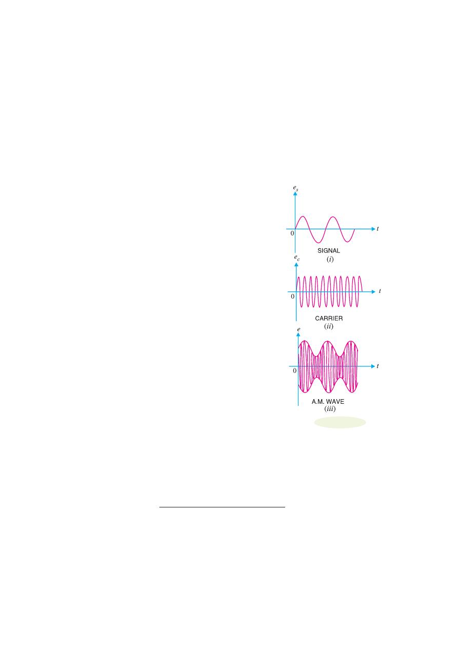
In amplitude modulation, only the amplitude of the carrier wave
is changed in accordance with the intensity of the signal. However,
the frequency of the modulated wave remains the same i.e. carrier
frequency. Fig. 16.2 shows the principle of amplitude modulation.
Fig. 16.2 (i) shows the audio electrical signal whereas Fig. 16.2 (ii)
shows a carrier wave of constant amplitude. Fig. 16.2 (iii) shows
the amplitude modulated (AM) wave. Note that the amplitudes of
both positive and negative half-cycles of carrier wave are changed in
accordance with the signal. For instance, when the signal is increas-
ing in the positive sense, the amplitude of carrier wave also increases.
On the other hand, during negative half-cycle of the signal, the am-
plitude of carrier wave decreases. Amplitude modulation is done by
an electronic circuit called
modulator.
The following points are worth noting in amplitude modulation :
(i)
The amplitude of the carrier wave changes according to the
intensity of the signal.
(ii)
The amplitude variations of the carrier wave is at the signal
frequency f
s
.
(iii)
The frequency of the amplitude modulated wave remains
the same i.e. carrier frequency f
c
.
16.5 Modulation Factor
An important consideration in amplitude modulation is to describe the depth of modulation i.e. the
extent to which the amplitude of carrier wave is changed by the signal. This is described by a factor
called modulation factor which may be defined as under :
The ratio of change of amplitude of carrier wave to the amplitude of normal carrier wave is
called the
modulation factor
m i.e.
Modulation factor, m =
Amplitude change of carrier wave
Normal carrier amplitude (unmodulated)
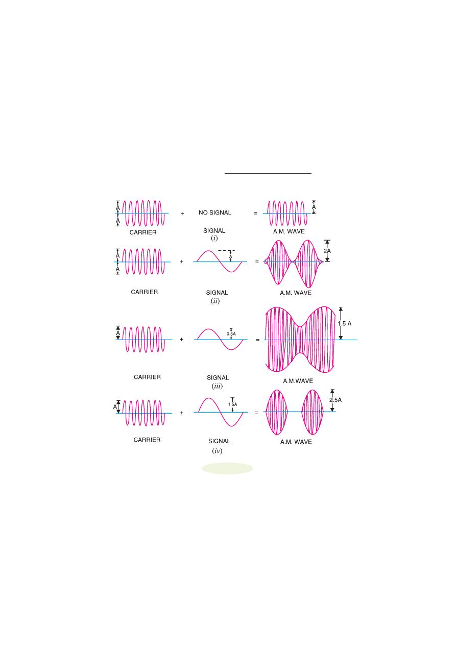
The value of modulation factor depends upon the amplitudes of carrier and signal. Fig. 16.3
shows amplitude modulation for different values of modulation factor m.
(i)
When signal amplitude is zero, the carrier wave is not modulated as shown in Fig. 16.3 (i).
The amplitude of carrier wave remains unchanged.
Fig. 16.2
Modulation And Demodulation
415
Amplitude change of carrier = 0
Amplitude of normal carrier = A
∴
Modulation factor, m = 0/A = 0 or 0%
(ii)
When signal amplitude is equal to the carrier amplitude as shown in Fig. 16.3 (ii), the
amplitude of carrier varies between 2A and zero.
Amplitude change of carrier = 2 A
− A = A
∴
Modulation factor, m =
Amplitude change of carrier
Amplitude of normal carrier
= A/A = 1 or 100 %
In this case, the carrier is said to be 100% modulated.
Fig. 16.3
(iii)
When the signal amplitude is one-half the carrier amplitude as shown in Fig. 16.3 (iii), the
amplitude of carrier wave varies between 1.5 A and 0.5 A.
Amplitude change of carrier = 1.5 A
− A = 0.5 A
∴
Modulation factor, m = 0.5 A/A = 0.5 or 50 %
In this case, the carrier is said to be 50% modulated.
(iv)
When the signal amplitude is 1.5 times the carrier amplitude as shown in Fig. 16.3 (iv), the
maximum value of carrier wave becomes 2.5 A.
Amplitude change of carrier wave = 2.5 A
− A = 1.5 A
416
Principles of Electronics
∴
Modulation factor, m =
1.5 A
A
= 1.5 or 150 %
In this case, the carrier is said to be 150% modulated i.e. over-modulated.
Importance of modulation factor.
Modulation factor is very important since it determines the
strength and quality of the transmitted signal. In an AM wave, the signal is contained in the variations
of the carrier amplitude. When the carrier is modulated to a small degree (i.e. small m), the amount
of carrier amplitude variation is small. Consequently, the audio signal being transmitted will not be
very strong. The greater the degree of modulation (i.e. m), the stronger and clearer will be the audio
signal. It may be emphasised here that if the carrier is overmodulated (i.e. m > 1), distortion will occur
during reception. This condition is shown in Fig. 16.3 (iv). The AM waveform is clipped and the
envelope is discontinuous. Therefore, degree of modulation should never exceed 100%.
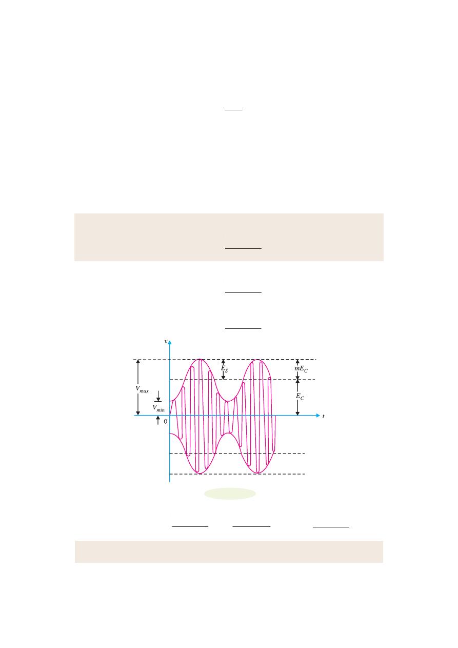
Example 16.1.
If the maximum and minimum voltage of an AM wave are V
max
and V
min
respec-
tively, then show that modulation factor m is given by :
m =
max
min
max
min
V
V
V
V
−
+
Solution.
Fig. 16.4 shows the waveform of amplitude modulated wave. Let the amplitude of the
normal carrier wave be E
C
. Then, it is clear from Fig. 16.4 that :
E
C
=
2
max
min
V
V
+
If E
S
is the signal amplitude, then it is clear from Fig. 16.4 that :
E
S
=
2
max
min
V
V
−
Fig. 16.4
But
E
S
= m E
C
or
2
max
min
V
V
−
= m
2
max
min
V
V
+
or m =
max
min
max
min
V
V
V
V
−
+
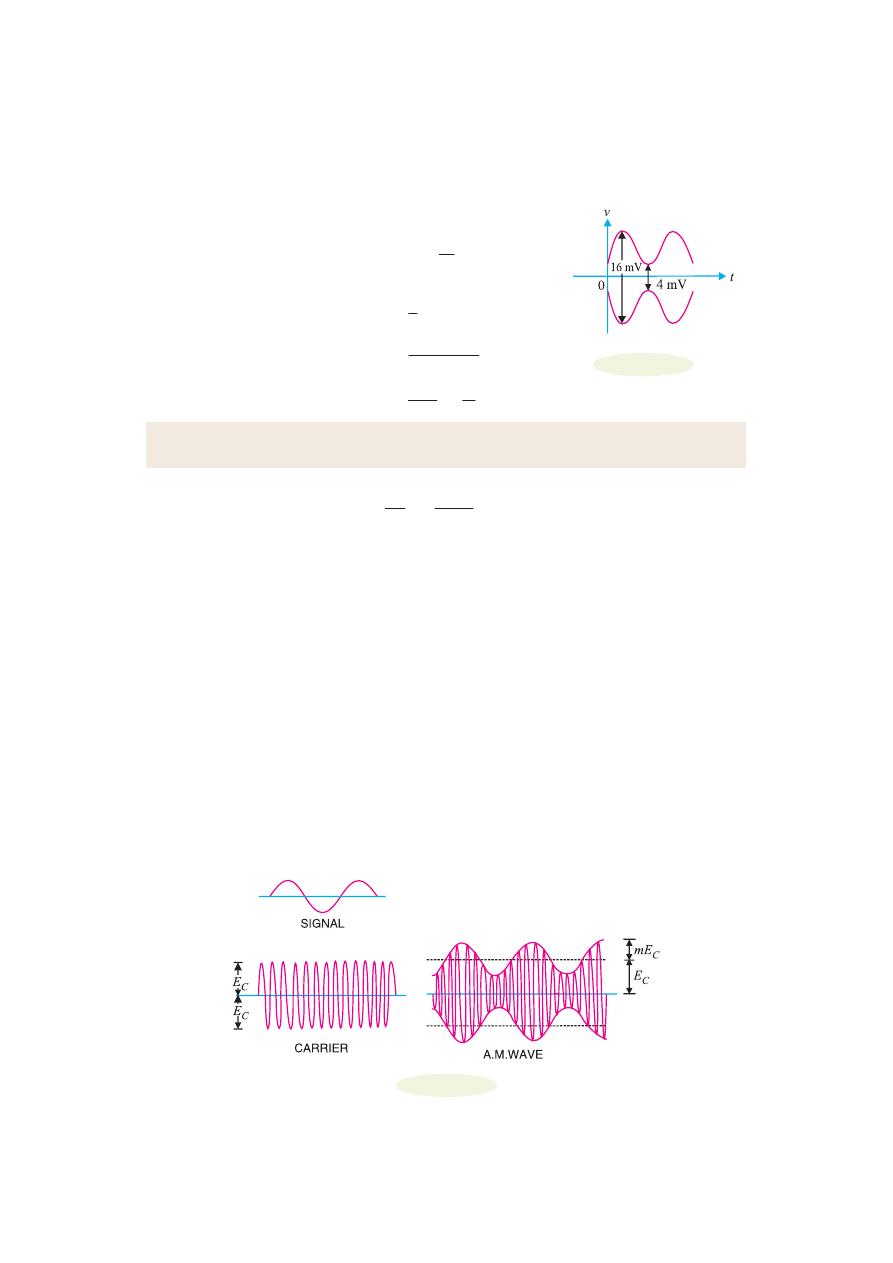
Example 16.2.
The maximum peak-to-peak voltage of an AM wave is 16 mV and the minimum
peak-to-peak voltage is 4 mV. Calculate the modulation factor.
Modulation And Demodulation
417
Solution.
Fig. 16.5 shows the conditions of the problem.
Maximum voltage of AM wave is
V
max
=
6
2
1
= 8 mV
Minimum voltage of AM wave is
V
min
=
4
2
= 2 mV
∴
Modulation factor, m =
max
min
max
min
V
V
V
V
−
+
=
8 2
6
8 2
10
− =
+
=
0.6
Example 16.3.
A carrier of 100V and 1200 kHz is modulated by a 50 V, 1000 Hz sine wave
signal. Find the modulation factor.
Solution.
Modulation factor, m =
50 V
100 V
S
C
E
E
=
=
0.5
16.6 Analysis of Amplitude Modulated Wave
A carrier wave may be represented by :
e
c
= E
C
cos
ω
c
t
where
e
c
= instantaneous voltage of carrier
E
C
= amplitude of carrier
ω
c
= 2
π f
c
= angular velocity at carrier frequency f
c
In amplitude modulation, the amplitude E
C
of the carrier wave is varied in accordance with the
intensity of the signal as shown in Fig. 16.6. Suppose the modulation factor is m. It means that signal
produces a maximum change of m E
C
in the carrier amplitude. Obviously, the amplitude of signal is
m E
C
. Therefore, the signal can be represented by :
e
s
= m E
C
cos
ω
s
t
where
e
s
= instantaneous voltage of signal
m E
C
= amplitude of signal
ω
s
= 2
π f
s
= angular velocity at signal frequency f
s
Fig. 16.6
Fig. 16.5
418
Principles of Electronics
The amplitude of the carrier wave varies at signal frequency f
s
. Therefore, the amplitude of AM
wave is given by :
Amplitude of AM wave = E
C
+ m E
C
cos
ω
s
t = E
C
(1 + m cos
ω
s
t)
The instantaneous voltage of AM wave is :
e = Amplitude
× cos ω
c
t
= E
C
(1 + m cos
ω
s
t) cos
ω
c
t
= E
C
cos
ω
c
t + m E
C
cos
ω
s
t cos
ω
c
t
= E
C
cos
ω
c
t +
2
C
mE
(2 cos
ω
s
t cos
ω
c
t)
= E
C
cos
ω
c
t +
2
C
mE
[cos (
ω
c
+
ω
s
) t + cos (
ω
c
− ω
s
) t]
*
= E
C
cos
ω
c
t +
2
C
mE
cos (
ω
c
+
ω
s
) t +
2
C
mE
cos (
ω
c
− ω
s
) t
The following points may be noted from the above equation of amplitude modulated wave:
(i)
The AM wave is equivalent to the summation of three sinusoidal waves; one having ampli-
tude E
C
and frequency
**
f
c
, the second having amplitude mE
C
/2 and frequency (f
c
+ f
s
) and the third
having amplitude mE
C
/2 and frequency f
c
− f
s
.
(ii)
The AM wave contains three frequencies viz f
c
, f
c
+ f
s
and f
c
− f
s
. The first frequency is the
carrier frequency. Thus, the process of modulation does not change the original carrier frequency but
produces two new frequencies (f
c
+ f
s
) and (f
c
− f
s
) which are called sideband frequencies.
(iii)
The sum of carrier frequency and signal frequency i.e. (f
c
+ f
s
) is called
upper sideband
frequency
. The
lower sideband frequency
is f
c
− f
s
i.e. the difference between carrier and signal
frequencies.
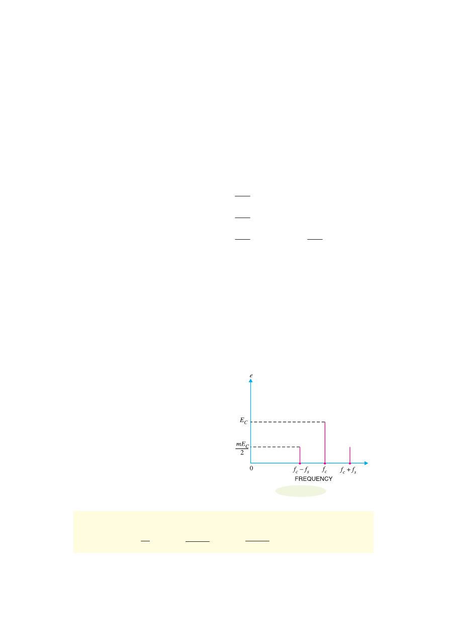
16.7 Sideband Frequencies in AM Wave
In an amplitude modulated wave, the sideband fre-
quencies are of our interest. It is because the signal
frequency f
s
is contained in the sideband frequen-
cies. Fig. 16.7 shows the frequency spectrum of an
amplitude modulated wave. The frequency com-
ponents in the AM wave are shown by vertical lines.
The height of each vertical line is equal to the am-
plitude of the components present. It may be added
here that in practical radio transmission, carrier fre-
quency f
c
is many times greater than signal fre-
quency f
s
. Hence, the sideband frequencies are gen-
erally close to the carrier frequency. It may be seen
that a carrier modulated by a single frequency is
equivalent to three simultaneous signals; the car-
*
From trigonometry, we have the expansion formula :
2 cos A cos B = cos (A + B) + cos (A
− B)
**
f
c
=
ω
2 π
c
, f
c
+ f
s
=
ω
ω
2 π
c
s
+
, f
c
− f
s
=
ω
ω
2 π
c
s
−
○
○
○
○
○
○
○
○
○
○
○
○
○
○
○
○
○
○
○
○
○
○
○
○
○
○
○
○
○
○
○
○
○
○
○
○
○
○
○
○
○
○
○
○
○
○
○
○
○
○
Fig. 16.7
Modulation And Demodulation
419
rier itself and two other steady frequencies i.e. f
c
+ f
s
and f
c
− f
s
.
Let us illustrate sideband frequencies with an example. Suppose the carrier frequency is 400
kHz and the signal frequency is 1 kHz. The AM wave will contain three frequencies viz 400 kHz, 401
kHz and 399 kHz. It is clear that upper sideband frequency (401 kHz) and lower sideband frequency
(399 kHz) are very close to the carrier frequency (400 kHz).
Bandwidth.
In an AM wave, the bandwidth is from (f
c
− f
s
) to (f
c
+ f
s
) i.e., 2 f
s
. Thus in the above
example, bandwidth is from 399 to 401 kHz or 2 kHz which is twice the signal frequency. Therefore,
we arrive at a very important conclusion that
in amplitude modulation, bandwidth is twice the signal
frequency
. The tuned amplifier which is called upon to amplify the modulated wave must have the
required bandwidth to include the sideband frequencies. If the tuned amplifier has insufficient band-
width, the upper sideband frequencies may not be reproduced by the radio receiver.
Example 16.4.
A 2500 kHz carrier is modulated by audio signal with frequency span of 50
−
15000 Hz. What are the frequencies of lower and upper sidebands ? What bandwidth of RF ampli-
fier is required to handle the output ?
Solution.
The modulating signal (e.g. music) has a range of 0.05 to 15 kHz. The sideband
frequencies produced range from f
c
± 0.05 kHz to f
c
± 15 kHz. Therefore, upper sideband ranges
from 2500.05 to 2515 kHz and lower sideband ranges from 2499.95 to 2485 kHz.
The sideband frequencies produced can be approximately expressed as 2500 ± 15 kHz. There-
fore, bandwidth requirement = 2515
− 2485 = 30 kHz. Note that bandwidth of RF amplifier required
is twice the frequency of highest modulating signal frequency.
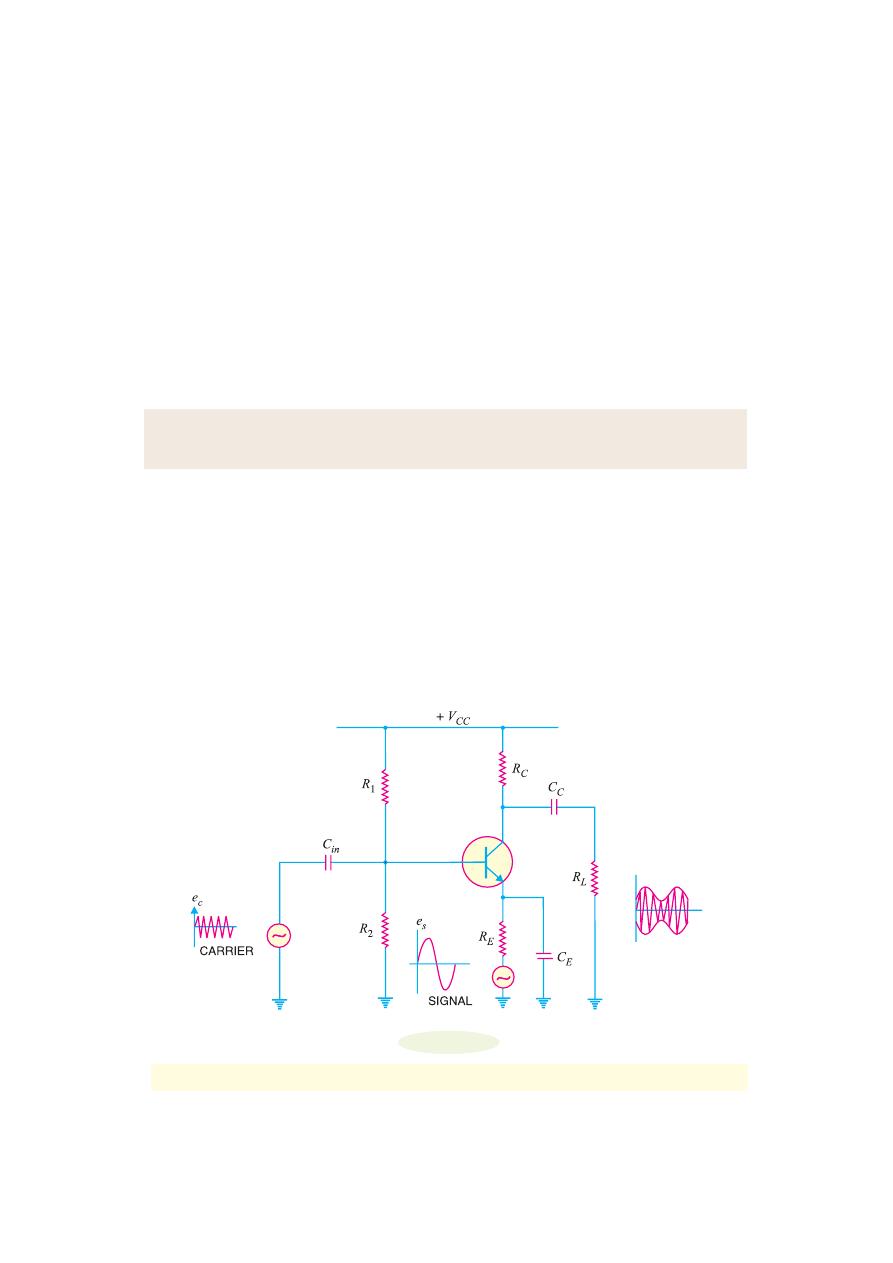
16.8 Transistor AM
*
Modulator
Fig. 16.8 shows the circuit of a simple AM modulator. It is essentially a CE amplifier having a
voltage gain of A. The carrier signal is the input to the amplifier. The modulating signal is applied in
the emitter resistance circuit.
Fig. 16.8
*
A circuit which does amplitude modulation is called AM modulator.
○
○
○
○
○
○
○
○
○
○
○
○
○
○
○
○
○
○
○
○
○
○
○
○
○
○
○
○
○
○
○
○
○
○
○
○
○
○
○
○
○
○
○
○
○
○
○
○
○
○

420
Principles of Electronics
Working.
The carrier e
c
is applied at the input of the amplifier and the modulating signal e
s
is
applied in the emitter resistance circuit. The amplifier circuit amplifies the carrier by a factor “A” so
that the output is Ae
c
. Since the modulating signal is a part of the biasing circuit, it produces low-
frequency variations in the emitter circuit. This in turn causes
*
variations in “A”. The result is that
amplitude of the carrier varies in accordance with the strength of the signal. Consequently, amplitude
modulated output is obtained across R
L
. It may be noted that carrier should not influence the voltage
gain A; only the modulating signal should do this. To achieve this objective, carrier should have a
small magnitude and signal should have a large magnitude.
Example 16.5.
An AM wave is represented by the expression :
v = 5 (1 + 0.6 cos 6280 t) sin 211
× 10
4
t volts
(i) What are the minimum and maximum amplitudes of the AM wave ?
(ii) What frequency components are contained in the modulated wave and what is the ampli-
tude of each component?
Solution.
The AM wave equation is given by : v = 5 (1 + 0.6 cos 6280 t) sin 211
× 10
4
t volts
...(i)
Compare it with standard AM wave eq., v = E
C
(1 + m cos
ω
s
t) sin
ω
c
t
...(ii)
From eqs. (i) and (ii) , we get,
E
C
= carrier amplitude = 5 V
m = modulation factor = 0.6
f
s
= signal frequency =
ω
s
/2
π = 6280/2π = 1 kHz
f
c
= carrier frequency =
ω
c
/2
π = 211 × 10
4
/2
π = 336 kHz
(i)
Minimum amplitude of AM wave = E
C
− mE
C
= 5
− 0.6 × 5 =
2 V
Maximum amplitude of AM wave = E
C
+ mE
C
= 5 + 0.6
× 5 =
8 V
(ii)
The AM wave will contain three frequencies viz.
f
c
− f
s
,
f
c
,
f
c
+ f
s
or
336
− 1 ,
336 ,
336 + 1
or
335 kHz,
336 kHz,
337 kHz
The amplitudes of the three components of AM wave are :
2
C
mE
,
E
C
,
2
C
mE
or
0.6 5
2
×
,
5,
0.6 5
2
×
or
1.5 V,
5 V,
1.5 V
Example 16.6.
A sinusoidal carrier voltage of frequency 1 MHz and amplitude 100 volts is
amplitude modulated by sinusoidal voltage of frequency 5 kHz producing 50% modulation. Calcu-
late the frequency and amplitude of lower and upper sideband terms.
Solution.
Frequency of carrier, f
c
= 1 MHz = 1000 kHz
Frequency of signal, f
s
= 5 kHz
Modulation factor, m = 50% = 0.5
*
The principle of this circuit is to change the gain A (and hence the amplitude of carrier) by the modulat-
ing signal.
○
○
○
○
○
○
○
○
○
○
○
○
○
○
○
○
○
○
○
○
○
○
○
○
○
○
○
○
○
○
○
○
○
○
○
○
○
○
○
○
○
○
○
○
○
○
○
○
○
○
Modulation And Demodulation
421
Amplitude of carrier, E
C
= 100 V
The lower and upper sideband frequencies are :
f
c
− f
s
and f
c
+ f
s
or
(1000
− 5) kHz and (1000 + 5) kHz
or
995 kHz
and
1005 kHz
Amplitude of each sideband term =
0.5 100
2
2
C
mE
×
=
=
25 V
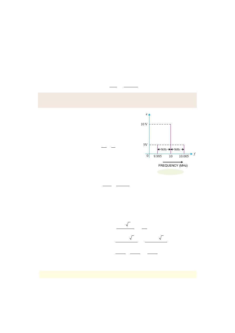
Example 16.7.
A carrier wave of frequency 10 MHz and peak value 10V is amplitude modu-
lated by a 5- kHz sine wave of amplitude 6V. Determine (i) modulation factor (ii) sideband frequen-
cies and (iii) amplitude of sideband components. Draw the frequency spectrum.
Solution.
Carrier amplitude, E
C
= 10V
Signal amplitude, E
S
= 6V
Carrier frequency, f
c
= 10 MHz
Signal frequency, f
s
= 5 kHz = 0.005 MHz
(i)
Modulation factor, m =
6
10
=
S
C
E
E
=
0.6
(ii)
Sideband frequencies are :
f
c
– f
s
; f
c
+ f
s
10 – 0.005 ; 10 + 0.005
9.995 MHz ; 10.005 MHz
(iii)
Amplitude of each sideband =
0.6 10
2
2
×
=
C
m E
=
3V
Fig. 16.9 shows the frequency spectrum of the A.M. wave.
16.9 Power in AM Wave
The power dissipated in any circuit is a function of the square of voltage across the circuit and the
effective resistance of the circuit. Equation of AM wave reveals that it has three components of
amplitude E
C
, m E
C
/2 and m E
C
/2. Clearly, power output must be distributed among these components.
Carrier power, P
C
=
(
)
2
2
/ 2
2
=
C
C
E
E
R
R
...(i)
Total power of sidebands, P
S
=
(
)
(
)
2
2
/ 2 2
/ 2 2
C
C
m E
m E
R
R
+
=
2
2
2
2
2
2
8
8
4
C
C
C
m E
m E
m E
R
R
R
+
=
...(ii)
Total power of AM wave, P
T
= P
C
+ P
S
*
r.m.s. values are considered.
○
○
○
○
○
○
○
○
○
○
○
○
○
○
○
○
○
○
○
○
○
○
○
○
○
○
○
○
○
○
○
○
○
○
○
○
○
○
○
○
○
○
○
○
○
○
○
○
○
○
*
Fig. 16.9

422
Principles of Electronics
=
2
2
2
2
2
1
2
4
2
2
C
C
C
E
m E
E
m
R
R
R
⎡
⎤
+
=
+
⎢
⎥
⎣
⎦
or
P
T
=
2
2
2
2
2
C
m
E
R
⎡
⎤
+
⎣
⎦
...(iii)
Fraction of total power carried by sidebands is
S
T
P
P
=
2
2
Exp. ( )
Exp. ( )
2
ii
m
iii
m
=
+
....(iv)
As the signal is contained in the sideband frequencies, therefore, useful power is in the side-
bands. Inspection of exp. (iv) reveals that sideband power depends upon the modulation factor m.
The greater the value of m, the greater is the useful power carried by the sidebands. This emphasises
the importance of modulation factor.
(i)
When m = 0 , power carried by sidebands = 0
2
/2 + 0
2
= 0
(ii)
When m = 0.5, power carried by sidebands
=
2
2
(0.5)
2
(0.5)
+
= 11.1 % of total power of AM wave
(iii)
When m = 1, power carried by sidebands
=
2
2
(1)
2
(1)
+
= 33.3% of total power of AM wave
As an example, suppose the total power of an AM wave is 600 watts and modulation is 100%.
Then sideband power is 600/3 = 200 watts and carrier power will be 600
− 200 = 400 watts.
The sideband power represents the signal content and the carrier power is that power which is
required as the means of transmission.
Note.
P
C
=
2
2
C
E
R
and P
S
=
2 2
4
C
m E
R
∴
S
C
P
P
=
2
1
2
m
or
P
S
=
2
1
2
C
m P
...(v)
Expression (v) gives the relation between total sideband power (P
S
) and carrier power ( P
C
).
16.10 Limitations of Amplitude Modulation
Although theoretically highly effective, amplitude modulation suffers from the following drawbacks:
(i) Noisy reception.
In an AM wave, the signal is in the amplitude variations of the carrier.
Practically all the natural and man made noises consist of electrical amplitude disturbances. As a
radio receiver cannot distinguish between amplitude variations that represent noise and those that
contain the desired signal, therefore, reception is generally noisy.
(ii) Low efficiency.
In amplitude modulation, useful power is in the sidebands as they contain
the signal. As discussed before, an AM wave has low sideband power. For example, if modulation is
100%, the sideband power is only one-third of the total power of AM wave. Hence the efficiency of
this type of modulation is low.
Modulation And Demodulation
423
(iii) Small operating range.
Due to low efficiency of amplitude modulation, transmitters em-
ploying this method have a small operating range i.e. messages cannot be transmitted over larger
distances.
(iv) Lack of audio quality.
This is a distinct disadvantage of amplitude modulation. In order to
attain high-fidelity reception, all audio frequencies up to 15 kHz must be reproduced. This necessi-
tates bandwidth of 30 kHz since both sidebands must be reproduced. But AM broadcasting stations
are assigned bandwidth of only 10 kHz to minimise the interference from adjacent broadcasting
stations. This means that the highest modulating frequency can be 5 kHz which is hardly sufficient to
reproduce the music properly.
Example 16.8.
A carrier wave of 500 watts is subjected to 100% amplitude modulation.
Determine :
(i) power in sidebands (ii) power of modulated wave.
Solution.
(i)
Sideband power, P
S
=
2
1
1 500
2
2
C
m P
=
×
=
250 W
Thus there are 125 W in upper sideband and 125 W in lower sideband.
(ii)
Power of AM wave, P
T
= P
C
+ P
S
= 500 + 250 =
750 W
Example 16.9.
A 50 kW carrier is to be modulated to a level of (i) 80% (ii) 10%. What is the
total sideband power in each case ?
Solution. (i)
P
S
=
2
2
1
1 (0.8) 50
2
2
C
m P
=
×
=
16 kW
(ii)
P
S
=
2
2
1
1 (0.1) 50
2
2
C
m P
=
×
=
0.25 kW
Note the effect of modulation factor on the magnitude of sideband power. In the first case
(m = 80%), we generated and transmitted 50 kW carrier in order to send 16 kW of intelligence. In the
second case (m = 10%), the same carrier level — 50 kW — is used to send merely 250 W of intelli-
gence. Clearly, the efficiency of operation decreases rapidly as modulation factor decreases. For this
reason, in amplitude modulation, the value of m is kept as close to unity as possible.
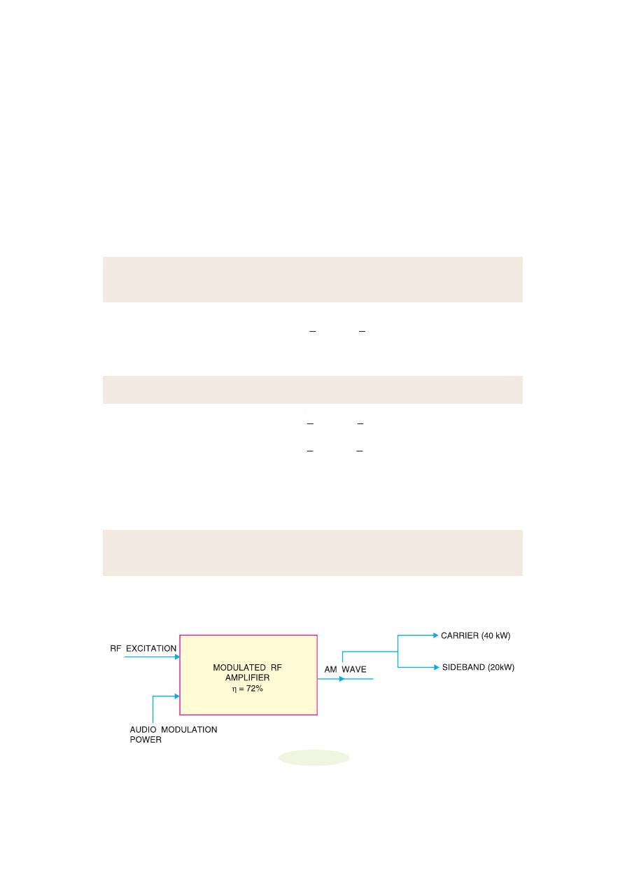
Example 16.10.
A 40kW carrier is to be modulated to a level of 100%.
(i) What is the carrier power after modulation ?
(ii) How much audio power is required if the efficiency of the modulated RF amplifier is 72% ?
Solution.
Fig. 16.10 shows the block diagram indicating the power relations.
(i)
Since the carrier itself is unaffected by the modulating signal, there is no change in the
carrier power level.
Fig. 16.10

424
Principles of Electronics
∴
P
C
=
40 kW
(ii)
P
S
=
2
2
1
1 (1) 40
2
2
C
m P
=
×
= 20 kW
∴
P
audio
=
20
0.72
0.72
S
P
=
=
27.8 kW
Example 16.11.
An audio signal of 1 kHz is used to modulate a carrier of 500 kHz. Determine
(i) sideband frequencies (ii) bandwidth required.
Solution.
Carrier frequency, f
c
= 500 kHz
Signal frequency, f
s
= 1 kHz
(i)
As discussed in Art. 16.6, the AM wave has sideband frequencies of ( f
c
+ f
s
) and ( f
c
− f
s
).
∴
Sideband frequencies = (500 + 1) kHz and (500
− 1) kHz
=
501 kHz
and
499 kHz
(ii)
Bandwidth required = 499 kHz to 501 kHz =
2 kHz
Example 16.12.
The load current in the transmitting antenna of an unmodulated AM transmitter
is 8A. What will be the antenna current when modulation is 40% ?
Solution.
P
S
=
2
1
2
C
m P
P
T
= P
C
+ P
S
= P
C
2
1
2
m
⎛
⎞
+
⎜
⎟
⎝
⎠
∴
T
C
P
P
=
2
1
2
m
+
or
2
T
C
I
I
⎛
⎞
⎜
⎟
⎝
⎠
=
2
1
2
m
+
Given that I
C
= 8A; m = 0.4
∴
2
8
T
I
⎛
⎞
⎜
⎟
⎝
⎠
=
2
(0.4)
1
2
+
or
(I
T
/8)
2
= 1.08
or
I
T
=
8 1.08
=
8.31 A
Example 16.13.
The antenna current of an AM transmitter is 8A when only carrier is sent but it
increases to 8.93A when the carrier is sinusoidally modulated. Find the % age modulation.
Solution.
As shown in example 16.12,
2
T
C
I
I
⎛
⎞
⎜
⎟
⎝
⎠
=
2
1
2
m
+
Given that I
T
= 8.93 A; I
C
= 8 A ; m = ?
∴
( )
2
8.93
8
=
2
1
2
m
+
or
1.246 = 1 + m
2
/2
or
m
2
/2 = 0.246
or
m =
2 0.246
×
= 0.701 =
70.1%
Modulation And Demodulation
425
Example 16.14.
The r.m.s. value of carrier voltage is 100 V. After amplitude modulation by a
sinusoidal a.f. voltage, the r.m.s. value becomes 110 V. Calculate the modulation index.
Solution.
T
C
P
P
=
2
1
2
m
+
or
2
T
C
V
V
⎛
⎞
⎜
⎟
⎝
⎠
=
2
1
2
m
+
Given that V
T
= 110 V ; V
C
= 100 V ; m = ?
∴
( )
2
110
100
=
2
1
2
m
+
or
1.21 =
2
1
2
m
+
or
m
2
/2 = 0.21
or
m =
0.21 2
×
=
0.648
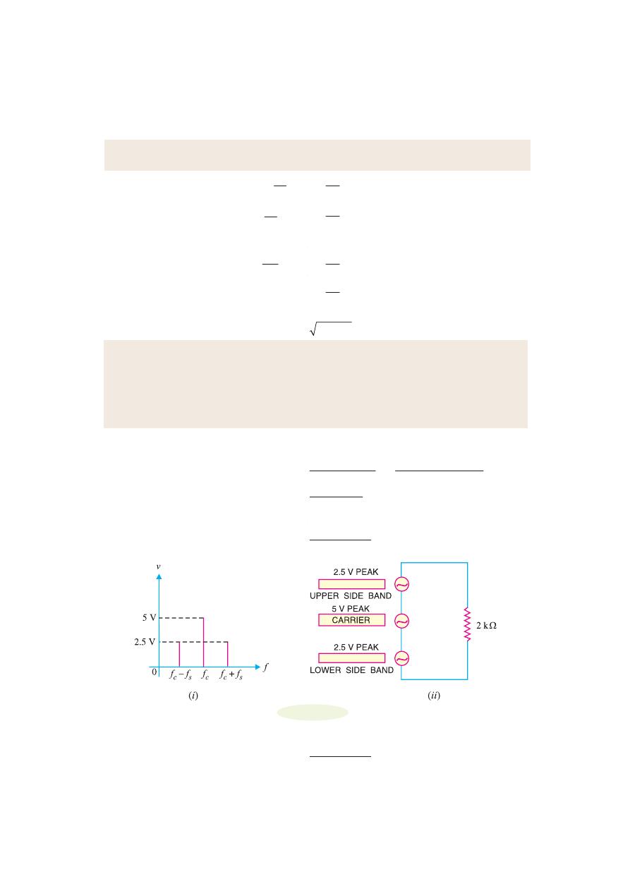
Example 16.15.
An AM wave consists of the following components :
Carrier component = 5 V peak value
Lower sideband component = 2.5 V peak value
Upper sideband component = 2.5 V peak value
If the AM wave drives a 2 k
Ω resistor, find the power delivered to the resistor by (i) carrier (ii)
lower sideband component and (iii) upper sideband component. What is the total power delivered?
Solution.
Fig. 16.11 (i) shows the frequency spectrum of AM wave whereas Fig. 16.11
(ii) shows the equivalent circuit.
Power =
2
2
(0.707 peak value)
(r.m.s. voltage)
R
R
×
=
(i)
Power delivered by the carrier, P
C
=
2
(0.707 5)
2000
×
=
6.25 mW
(ii)
Power delivered by lower sideband component is
P
lower
=
2
(0.707 2.5)
2000
×
=
1.562 mW
Fig. 16.11
(iii)
Power delivered by upper sideband component is
P
upper
=
2
(0.707 2.5)
2000
×
=
1.562 mW
426
Principles of Electronics
Total power delivered by the AM wave = 6.25 + 1.562 + 1.562 =
9.374 mW
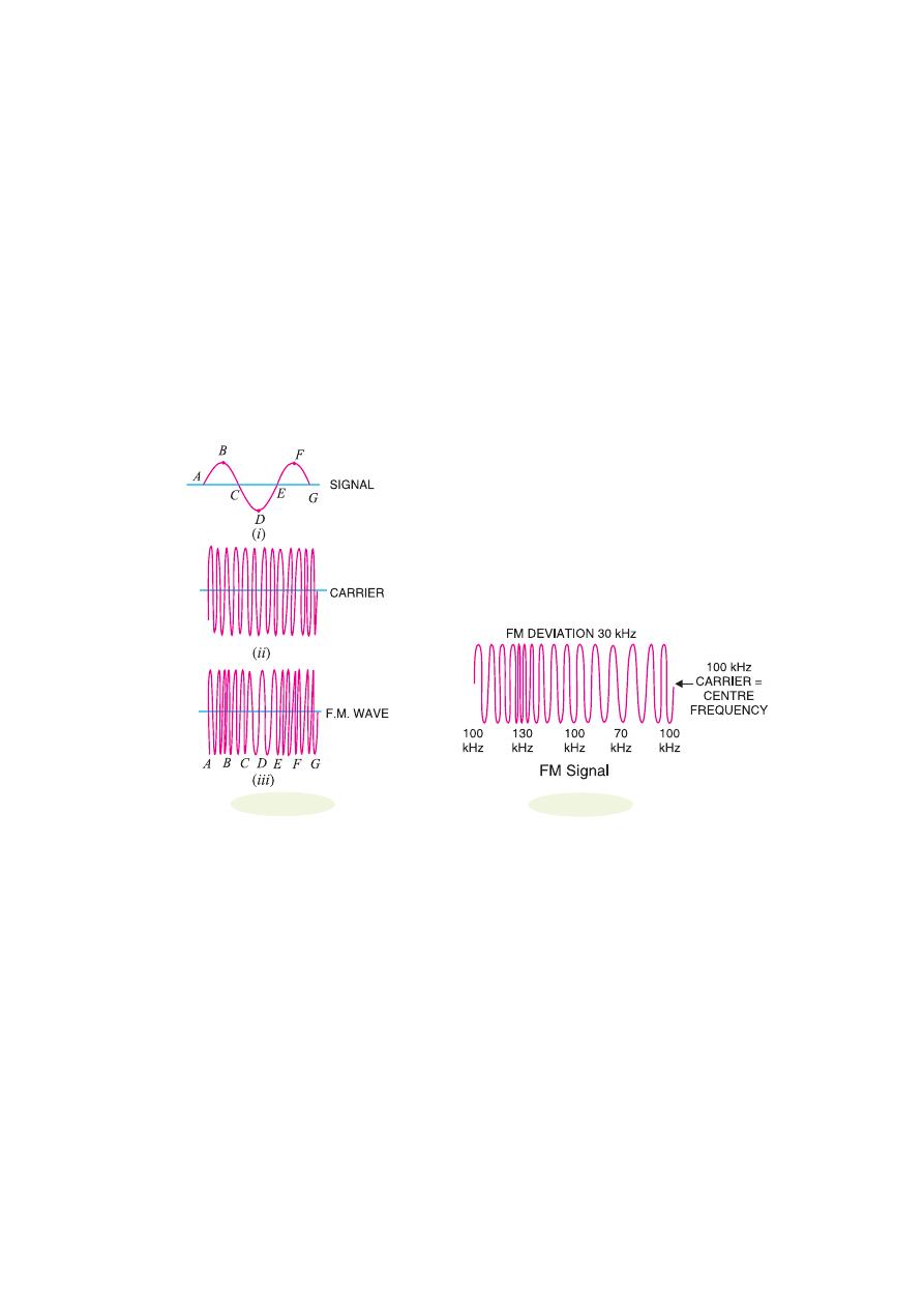
16.11 Frequency Modulation (FM)
When the frequency of carrier wave is changed in accordance with the intensity of the signal, it is
called
frequency modulation (FM)
.
In frequency modulation, only the frequency of the carrier wave is changed in accordance with
the signal. However, the amplitude of the modulated wave remains the same i.e. carrier wave ampli-
tude. The frequency variations of carrier wave depend upon the instantaneous amplitude of the signal
as shown in Fig. 16.12 (iii). When the signal voltage is zero as at A, C, E and G, the carrier frequency
is unchanged. When the signal approaches its positive peaks as at B and F, the carrier frequency is
increased to maximum as shown by the closely spaced cycles. However, during the negative peaks of
signal as at D, the carrier frequency is reduced to minimum as shown by the widely spaced cycles.
Illustration.
The process of frequency modulation (FM) can be made more illustrative if we
consider numerical values. Fig. 16.13 shows the FM signal having carrier frequency f
c
= 100 kHz.
Note that FM signal has constant amplitude but varying frequencies above and below the carrier
frequency of 100 kHz (= f
c
). For this reason, f
c
(= 100 kHz) is called
centre frequency.
The changes in
the carrier frequency are produced by the audio-modulating signal. The amount of change in fre-
quency from f
c
(= 100 kHz) or
frequency deviation
depends upon the amplitude of the audio-modu-
lating signal. The frequency deviation increases with the increase in the modulating signal and vice-
versa. Thus the peak audio voltage will produce maximum frequency deviation. Referring to Fig.
16.13, the centre frequency is 100 kHz and the maximum frequency deviation is 30 kHz. The follow-
ing points about frequency modulation (FM) may be noted carefully :
(a)
The frequency deviation of FM signal depends on the amplitude of the modulating signal.
(b)
The centre frequency is the frequency without modulation or when the modulating voltage is
zero.
(c)
The audio frequency (i.e. frequency of modulating signal) does not determine frequency
deviation.
Advantages :
The following are the advantages of FM over AM :
Fig. 16.12
Fig. 16.13
Modulation And Demodulation
427
(i)
It gives noiseless reception. As discussed before, noise is a form of amplitude variations and
a FM receiver will reject such signals.
(ii)
The operating range is quite large.
(iii)
It gives high-fidelity reception.
(iv)
The efficiency of transmission is very high.
16.12 T
T
T
T
Theor
heor
heor
heor
heory of
y of
y of
y of
y of F
F
F
F
Frrrrrequenc
equenc
equenc
equenc
equency Modula
y Modula
y Modula
y Modula
y Modulation (FM)
tion (FM)
tion (FM)
tion (FM)
tion (FM)
In frequency modulation (FM), the amplitude of the carrier is kept constant but the frequency f
c
of the
carrier is varied by the modulating signal. The carrier frequency f
c
varies at the rate of the
*
signal
frequency f
s
; the frequency deviation being proportional to the instantaneous amplitude of the modu-
lating signal. Note that maximum frequency deviation is (f
c (max)
– f
c
) and occurs at the peak voltage of
the modulating signal. Suppose we modulate a 100 MHz carrier by 1V, 1 kHz modulating signal and
the maximum frequency deviation is 25 kHz. This means that the carrier frequency will vary sinusoi-
dally between (100 + 0.025) MHz and (100 – 0.025) MHz at the rate of 1000 times per second. If the
amplitude of the modulating signal is increased to 2V, then the maximum frequency deviation will be
50 kHz and the carrier frequency will vary between (100 + 0.05) MHz and (100 – 0.05) MHz at the
rate of 1000 times per second.
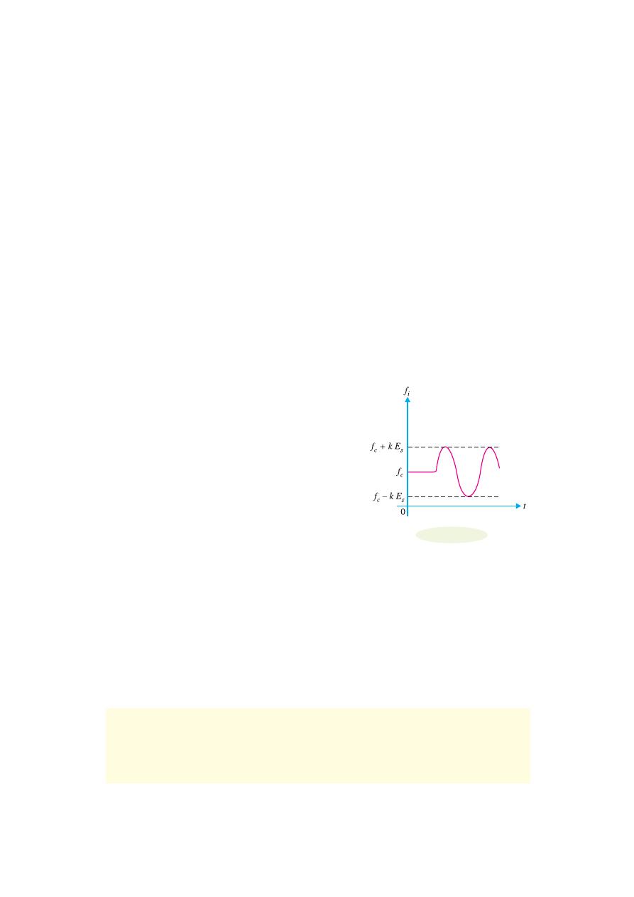
Suppose a modulating sine-wave signal e
s
(= E
s
cos
ω
s
t)
is used to vary the carrier frequency f
c
. Let the change in
carrier frequency be ke
s
where k is a constant known as the
frequency deviation constant.
The instantaneous carrier fre-
quency f
i
is given by ;
f
i
= f
c
+ k e
s
= f
c
+ k E
s
cos
ω
s
t
A graph of f
i
versus time is shown in Fig. 16.14. It is
important to note that it is frequency-time curve and not
amplitude-time curve. The factor k E
s
represents the maxi-
mum frequency deviation and is denoted by
Δf i.e.
Max. frequency deviation,
Δf =
**
k E
s
∴
f
i
= f
c
+
Δ f cos ω
s
t
Equation of FM wave.
In frequency modulation, the
carrier frequency is varied sinusoidally at signal frequency. The instantaneous deviation in frequency
from the carrier is proportional to the instantaneous amplitude of the modulating signal. Thus the
instantaneous angular frequency of FM is given by ;
ω
i
=
ω
c
+
Δω
c
cos
ω
s
t
Total phase angle
θ = ωt so that if ω is variable, then,
θ =
0
t
i
dt
ω
∫
=
0
(
cos
)
t
c
c
s
t dt
ω + Δω
ω
∫
*
Note this point. It means that modulating frequency is the rate of frequency of deviations in the RF
carrier. For example, all signals having the same amplitude will deviate the carrier frequency by the same
amount, say 50 kHz, no matter what their frequencies. On similar lines, all signals of the same frequency,
say, 3 kHz, will deviate the carrier at the same rate of 3000 times per second, no matter what their
individual amplitudes.
**
Note that k is in kHz or MHz per volt.
○
○
○
○
○
○
○
○
○
○
○
○
○
○
○
○
○
○
○
○
○
○
○
○
○
○
○
○
○
○
○
○
○
○
○
○
○
○
○
○
○
○
○
○
○
○
○
○
○
○
Fig. 16.14

428
Principles of Electronics
∴
θ = ω
c
t +
sin
c
s
s
t
Δω
ω
ω
The term
c
s
Δω
ω
is called
modulation index m
f
.
∴
θ = ω
c
t + m
f
sin
ω
s
t
The instantaneous value of FM voltage wave is given by ;
e = E
c
cos
θ
or
e = E
c
cos (
ω
c
t + m
f
sin
ω
s
t)
...(i)
Exp. (i) is the general voltage equation of a FM wave. The following points may be noted carefully :
(i)
The modulation index m
f
is the ratio of maximum frequency deviation (
Δf) to the frequency
(= f
s
) of the modulating signal i.e.
Modulation index, m
f
=
(
)
−
Δω
Δ
=
=
ω
c max
c
c
s
s
s
f
f
f
f
f
(ii)
Unlike amplitude modulation, the modulation index (m
f
) for frequency modulation can be
greater than unity.
Frequency Spectrum.
It requires advanced mathematics to derive the spectrum of FM wave.
We will give only the results without derivation. If f
c
and f
s
are the carrier and signal frequencies
respectively, then FM spectrum will have the following frequencies :
f
c
; f
c
± f
s
; f
c
± 2f
s
; f
c
± 3f
s
and so on.
Note that f
c
+ f
s
, f
c
+ 2f
s
, f
c
+ 3f
s
...... are the upper sideband frequencies while f
c
– f
s
, f
c
– 2f
s
,
f
c
– 3f
s
...... are the lower sideband frequencies.
Example 16.16.
A frequency modulated voltage wave is given by the equation :
e = 12 cos (6 × 10
8
t + 5 sin 1250 t)
Find (i) carrier frequency (ii) signal frequency (iii) modulation index (iv) maximum frequency
deviation (v) power dissipated by the FM wave in 10-ohm resistor.
Solution.
The given FM voltage wave is
e = 12 cos (6 × 10
8
t + 5 sin 1250 t)
...(i)
The equation of standard FM voltage wave is
e = E
c
cos (
ω
c
t + m
f
sin
ω
s
t)
...(ii)
Comparing eqs. (i) and (ii), we have,
(i)
Carrier frequency, f
c
=
8
6 10
2
2
c
ω
×
=
π
π
=
95.5 × 10
6
Hz
(ii)
Signal frequency, f
s
=
1250
2
2
s
ω
=
π
π
=
199 Hz
(iii)
Modulation index, m
f
=
5
(iv)
Max. frequency deviation,
Δf = m
f
× f
s
= 5 × 199 =
995 Hz
(v)
Power dissipated, P =
2
2
. . .
(12 / 2)
10
r m s
E
R
=
=
7.2W
Example 16.17.
A 25 MHz carrier is modulated by a 400 Hz audio sine wave. If the carrier
voltage is 4V and the maximum frequency deviation is 10 kHz, write down the voltage equation of the
FM wave.
Solution.
The voltage equation of the FM wave is
e = E
c
cos (
ω
c
t + m
f
sin
ω
s
t)

Modulation And Demodulation
429
Here
ω
c
= 2
π f
c
= 2
π × 25 × 10
6
= 1.57 × 10
8
rad/s
ω
s
= 2
π f
s
= 2
π × 400 = 2513 rad/s
m
f
=
3
10 kHz
10 × 10 Hz
=
400 Hz
400Hz
Δ =
s
f
f
= 25
∴
e = 4 cos (1.57 × 10
8
t + 25 sin 2513t)
Ans.
Example 16.18.
Calculate the modulation index for an FM wave where the maximum fre-
quency deviation is 50 kHz and the modulating frequency is 5 kHz.
Solution.
Max. frequency deviation,
Δf = 50 kHz
Modulating frequency, f
s
= 5 kHz
∴
Modulation index, m
f
=
50 kHz
5 kHz
s
f
f
Δ =
=
10
Example 16.19.
The carrier frequency in an FM modulator is 1000 kHz. If the modulating
frequency is 15 kHz, what are the first three upper sideband and lower sideband frequencies?
Solution.
Carrier frequency, f
c
= 1000 kHz
Modulating frequency, f
s
= 15 kHz
Upper sideband frequencies
f
c
+ f
s
;
f
c
+ 2 f
s
;
f
c
+ 3 f
s
1000 + 15
;
1000 + 2 × 15
;
1000 + 3 × 15
1015 kHz
;
1030 kHz
;
1045 kHz
Lower sideband frequencies
f
c
– f
s
;
f
c
– 2 f
s
;
f
c
– 3 f
s
1000 – 15
;
1000 – 2 × 15
;
1000 – 3 × 15
985 kHz
;
970 kHz
;
955 kHz
Example 16.20.
The carrier and modulating frequencies of an FM transmitter are 100 MHz
and 15 kHz respectively. If the maximum frequency deviation is 75 kHz, find the bandwidth of FM
signal.
Solution.
To calculate the exact bandwidth of an FM signal, it requires the use of advanced
mathematics (Bessel functions) which is beyond the level of this book. However, the bandwidth of an
FM signal is approximately given by ;
Bandwidth, BW = 2 [
Δf + f
s
] = 2 [75 + 15] =
180 kHz
Example 16.21.
In a frequency modulated wave, frequency deviation constant is 75 kHz/volt
and the signal amplitude is 2V. Find the maximum frequency deviation.
Solution.
Frequency deviation constant, k = 75 kHz/V
Amplitude of signal, E
s
= 2V
∴
Max. frequency deviation,
Δf = k E
s
= 75 × 2 =
150 kHz
Example 16.22.
In an FM system, when the audio frequency (AF) is 500 Hz and the AF voltage
is 2.4V, the frequency deviation is 4.8 kHz. If the AF voltage is now increased to 7.2V, what is the new
frequency deviation? If the AF voltage is raised to 10V while the AF is dropped to 200 Hz, what is the
deviation? Find the modulation index in each case.
430
Principles of Electronics
Solution.
We know that :
Frequency deviation,
Δf
1
= k E
s
∴
Frequency deviation constant, k =
1
4.8
2.4
s
f
E
Δ
=
= 2 kHz/V
For E
s
= 7.2V,
Δf
2
=2 × 7.2 =
14.4 kHz
For E
s
= 10V,
Δf
3
=2 × 10 =
20 kHz
The answer of
20 kHz
shows that deviation is independent of modulating frequency.
The modulation indices in the three cases are :
m
f1
=
1
1
4.8
0.5
s
f
f
Δ
=
=
9.6
m
f2
=
2
1
14.4
0.5
s
f
f
Δ
=
=
28.8
m
f3
=
3
2
20
0.2
s
f
f
Δ
=
=
100
It is important to note that for calculating modulation index, the modulating frequency change
had to be taken into account in the third case.
16.13 Comparison of FM and AM
The comparison of FM and AM is given in the table below.
S. No
1.
2.
3.
4.
FM
The amplitude of carrier remains constant
with modulation.
The carrier frequency changes with modu-
lation.
The carrier frequency changes according to
the strength of the modulating signal.
The value of modulation index (m
f
) can be
more than 1.
AM
The amplitude of carrier changes with
modulation.
The carrier frequency remains constant with
modulation.
The carrier amplitude changes according to
the strength of the modulating signal.
The value of modulation factor (m) cannot
be more than 1 for distortionless AM
signal.
16.14 Demodulation
The process of recovering the audio signal from the modulated wave is known as
demodulation
or
detection.
At the broadcasting station, modulation is done to transmit the audio signal over larger distances
to a receiver. When the modulated wave is picked up by the radio receiver, it is necessary to recover
the audio signal from it. This process is accomplished in the radio receiver and is called demodula-
tion.
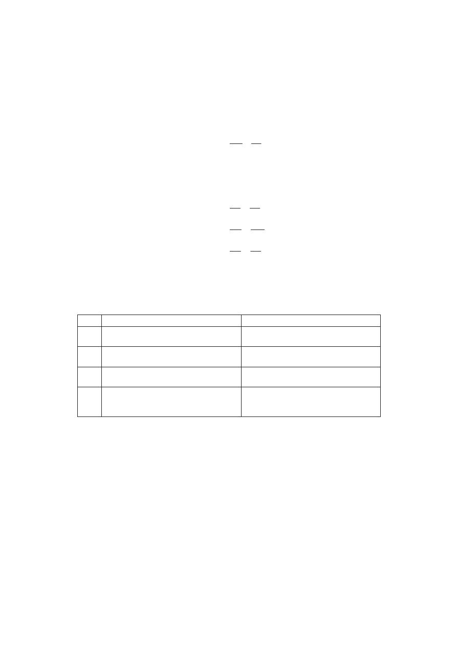
Necessity of demodulation.
It was noted previously that amplitude modulated wave consists of
carrier and sideband frequencies. The audio signal is contained in the sideband frequencies which
are radio frequencies. If the modulated wave after amplification is directly fed to the speaker as
shown in Fig. 16.15, no sound will be heard. It is because diaphragm of the speaker is not at all able
to respond to such high frequencies. Before the diaphragm is able to move in one direction, the rapid
reversal of current tends to move it in the opposite direction i.e. diaphragm will not move at all.
Consequently, no sound will be heard.
Modulation And Demodulation
431
Fig. 16.15
From the above discussion, it follows that audio signal must be separated from the carrier at a
suitable stage in the receiver. The recovered audio signal is then amplified and fed to the speaker for
conversion into sound.
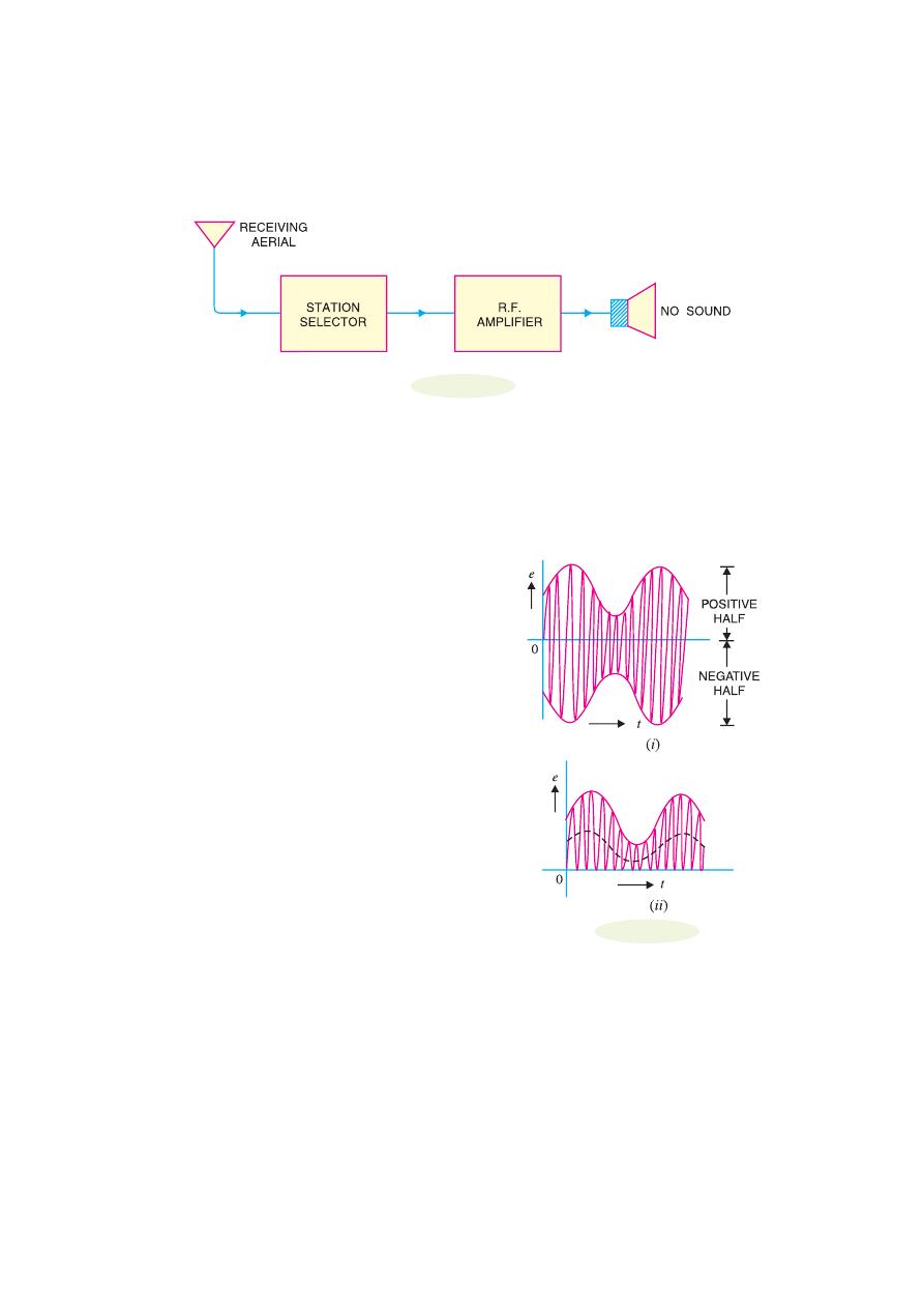
16.15 Essentials in Demodulation
In order that a modulated wave is audible, it is necessary to change the nature of modulated wave.
This is accomplished by a circuit called
detector.
A detector circuit performs the following two
functions :
(i) It rectifies the modulated wave i.e.
negative half
of the modulated wave is eliminated. As shown in Fig.
16.16 (i), a modulated wave has positive and negative
halves exactly equal. Therefore, average current is zero
and speaker cannot respond. If the negative half of this
modulated wave is eliminated as shown in Fig. 16.16 (ii),
the average value of this wave will not be zero since the
resultant pulses are now all in one direction. The average
value is shown by the dotted line in Fig. 16.16 (ii). There-
fore, the diaphragm will have definite displacement cor-
responding to the average value of the wave. It may be
seen that shape of the average wave is similar to that of
the modulation envelope. As the signal is of the same
shape as the envelope, therefore, average wave shape is
of the same form as the signal.
(ii) It separates the audio signal from the carrier.
The rectified modulated wave contains the audio signal
and the carrier. It is desired to recover the audio signal.
This is achieved by a filter circuit which removes the car-
rier frequency and allows the audio signal to reach the
load i.e.speaker.
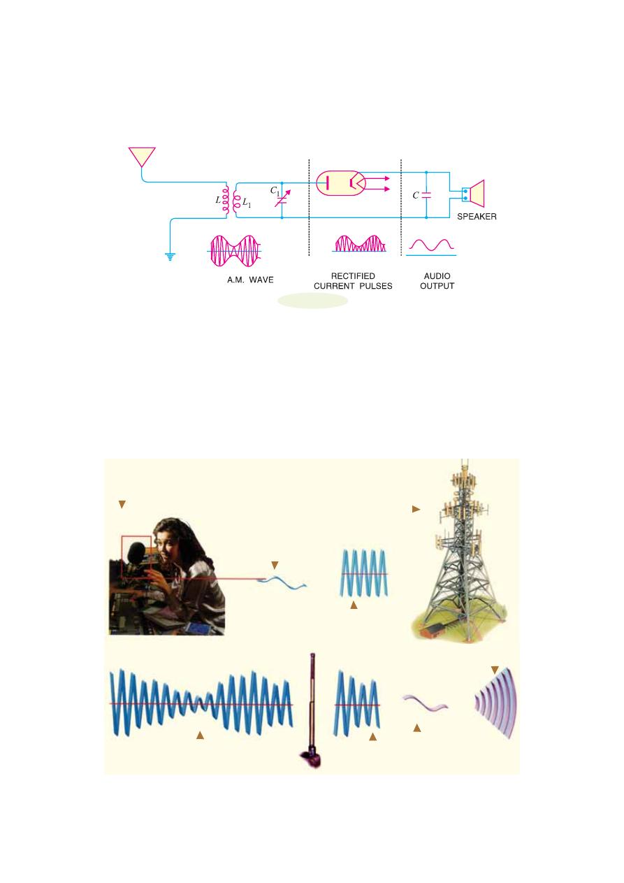
16.16 A.M. Diode Detector
Fig. 16.17 shows a simple detector circuit employing vacuum diode and filter circuit. The modulated
wave of desired frequency is selected by the parallel tuned circuit L
1
C
1
and is applied to the vacuum
diode. During the positive half-cycles of modulated wave, the diode conducts while during negative
half-cycles, it does not. The result of this rectifying action is that output of the diode consists of
positive half-cycles of modulated wave as shown.
Fig. 16.16
432
Principles of Electronics
Fig. 16.17
The rectified modulated wave contains radio frequency and the signal and cannot be fed to the
speaker for sound reproduction. If done so, no sound will be heard due to the inertia of speaker
diaphragm. The r.f. component is filtered by the capacitor C shunted across the speaker. The value of
this capacitor is sufficiently large to present low reactance to the r.f. component while presenting a
relatively high reactance to the audio signal. The result is that the r.f. component is bypassed by the
capacitor C and the signal is passed on to the speaker for sound reproduction.
Note
.
If vacuum diode is replaced by a crystal diode, the circuit becomes crystal diode detector.
16.17 A.M. Radio Receivers
A radio receiver is a device which reproduces the modulated or radio waves into sound waves. In
India, only amplitude modulation is used for radio transmission and reception. Therefore, such radio
The radio signal travels through the air and is
detected by all radio aerials within the range
of the transmitter.
A tuning circuit se-
lects the radio sig-
nal for decoding.
The sound signal is
decoded from the
combined signal.
An amplifier boosts the sound sig-
nal for loudspeakers, which turns
the signal back into sound.
In a studio at the radio sta-
tion programme presenter
talks into a microphone.
The microphone turns
sound waves into a vi-
brating electrical sig-
nal.
This signal is combined
with another signal, that
vibrates very rapidly.
The combined signals
are turned into radio
waves for transmission
from an antenna.
Modulation And Demodulation
433
receivers are called A.M. radio receivers. In order to reproduce the A.M. wave into sound waves,
every radio receiver must perform the following functions :
(i)
The receiving aerial must intercept a portion of the passing radio waves.
(ii)
The radio receiver must select the desired radio wave from a number of radio waves inter-
cepted by the receiving aerial. For this purpose, tuned parallel LC circuits must be used. These
circuits will select only that radio frequency which is in resonant with them.
(iii)
The selected radio wave must be amplified by the tuned frequency amplifiers.
(iv)
The audio signal must be recovered from the amplified radio wave.
(v)
The audio signal must be amplified by suitable number of audio-amplifiers.
(vi)
The amplified audio signal should be fed to the speaker for sound reproduction.
16.18 Types of A.M. Radio Receivers
A.M. radio receivers can be broadly classified into two types viz.,
straight radio receiver
and
superhetrodyne radio receiver.
The former was used in the early days of radio communication.
However at present, all radio receivers are of superhetrodyne type.
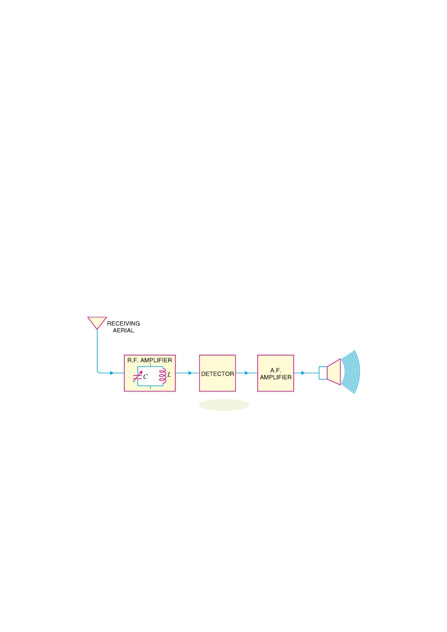
1. Straight radio receiver.
Fig. 16.18 shows the block diagram of a straight radio receiver.
The aerial is receiving radio waves from different broadcasting stations. The desired radio wave is
selected by the R.F. amplifier which employs a tuned parallel circuit. The selected radio wave is
amplified by the tuned r.f. amplifiers. The amplified radio wave is fed to the detector circuit. This
circuit extracts the audio signal from the radio wave. The output of the detector is the audio signal
which is amplified by one or more stages of audio-amplification. The amplified audio signal is fed to
the speaker for sound reproduction.
Fig. 16.18
Limitations.
(i)
In straight radio receivers, tuned circuits are used. As it is necessary to change the value of
variable capacitors (gang capacitors) for tuning to the desired station, therefore, there is a consider-
able variation of Q between the closed and open positions of the variable capacitors. This changes
the sensitivity and selectivity of the radio receivers.
(ii)
There is too much interference of adjacent stations.
2. Superhetrodyne receiver.
The shortcomings of straight radio receiver were overcome by
the invention of superhetrodyne receiver by Major Edwin H. Armstrong during the First World War.
At present, all modern receivers utilise the superhetrodyne circuit. In this type of radio receiver, the
selected radio frequency is converted to a fixed lower value, called
intermediate frequency (IF)
. This
is achieved by a special electronic circuit called
mixer circuit.
There is a local oscillator in the radio
receiver itself. This oscillator produces high frequency waves. The selected radio frequency is
mixed with the high frequency wave by the mixer circuit. In this process, beats are produced and the
mixer produces a frequency equal to the difference between local oscillator and radio wave fre-
434
Principles of Electronics
*
In a super-hetrodyne receiver, the hetrodyne principle is used to produce an intermediate frequency
which is higher than that can be heard i.e., supersonic. Superhetrodyne is short for supersonic hetrodyne.
○
○
○
○
○
○
○
○
○
○
○
○
○
○
○
○
○
○
○
○
○
○
○
○
○
○
○
○
○
○
○
○
○
○
○
○
○
○
○
○
○
○
○
○
○
○
○
○
○
○
quency
. As explained later, the circuit is so designed that oscillator always produces a frequency 455
kHz above the selected radio frequency. Therefore, the mixer will always produce an intermediate
frequency of 455 kHz regardless of the station to which the receiver is tuned. For instance, if 600 kHz
station is tuned, then local oscillator will produce a frequency of 1055 kHz. Consequently, the output
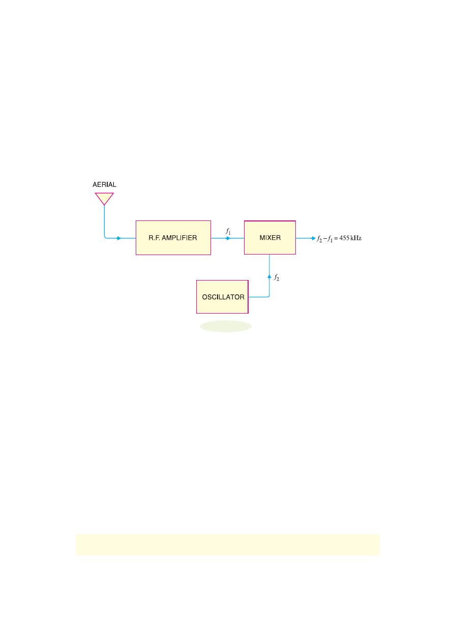
from the mixer will have a frequency of 455 kHz. Fig. 16.19 shows the superhetrodyne principle with
a block diagram. The selected radio frequency f
1
is mixed with a frequency f
2
from a local oscillator.
The output from the mixer is a difference (i.e. f
2
– f
1
) and is always 455 kHz regardless of the station
to which the receiver is tuned.
Fig. 16.19
The production of fixed intermediate frequency (455 kHz) is the salient feature of superhetrodyne
circuit. At this fixed intermediate frequency, the amplifier circuits operate with maximum stability,
selectivity and sensitivity. As the conversion of incoming radio frequency to the intermediate fre-
quency is achieved by
heterodyning
or beating the local oscillator against radio frequency, therefore,
this circuit is called
*
superhetrodyne circuit.
16.19 Stages of Superhetrodyne Radio Receiver
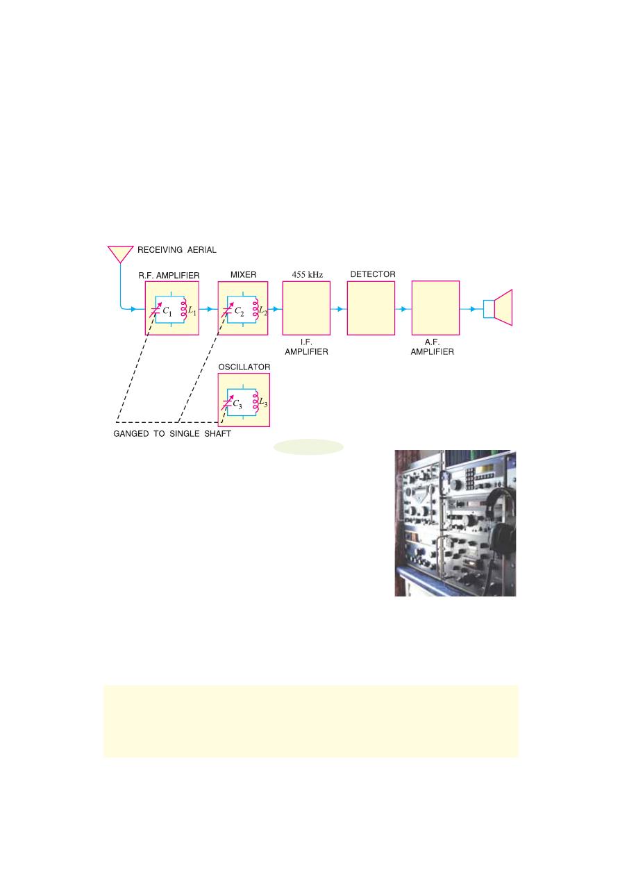
Fig. 16.20 shows the block diagram of a superhetrodyne receiver. It may be seen that R.F. amplifier
stage, mixer stage and oscillator stage use tuned parallel circuits with variable capacitors. These
capacitors are ganged together as shown by the dotted interconnecting lines. The rotation of the
common shaft simultaneously changes the capacitance of these tuned circuits.
(i) R.F. amplifier stage.
The R.F. amplifier stage uses a tuned parallel circuit L
1
C
1
with a
variable capacitor C
1
. The radio waves from various broadcasting stations are intercepted by the
receiving aerial and are coupled to this stage. This stage selects the desired radio wave and raises the
strength of the wave to the desired level.
(ii) Mixer stage.
The amplified output of R.F. amplifier is fed to the mixer stage where it is
combined with the output of a local oscillator. The two frequencies beat together and produce an
intermediate frequency (IF). The intermediate frequency is the difference between oscillator fre-
quency and radio frequency i.e.
I.F. = Oscillator frequency
− Radio frequency
Modulation And Demodulation
435
The IF is always 455 kHz regardless of the frequency to which the receiver is tuned. The reason
why the mixer will always produce 455 kHz frequency above the radio frequency is that oscillator
always produces a frequency 455 kHz
*
above the selected radio frequency. This is achieved by
making C
3
smaller than C
1
and C
2
. By making C
3
smaller, oscillator will tune to a higher frequency.
In practice, capacitance of C
3
is designed to tune the oscillator to a frequency higher than radio wave
frequency by 455 kHz. This frequency difference (i.e. 455 kHz) will always be maintained because
when C
1
and C
2
are varied, C
3
will also vary proportionally. It may be noted that in mixer stage, the
carrier frequency is reduced. The IF still contains the audio signal.
Fig. 16.20
(iii) I.F. amplifier stage.
The output of mixer is always 455
kHz and is fed to fixed tuned I.F. amplifiers. These amplifiers are
tuned to one frequency (i.e. 455 kHz) and render nice amplification.
(iv) Detector stage.
The output from the last IF amplifier stage
is coupled to the input of the detector stage. Here, the audio signal is
extracted from the IF output. Usually, diode detector circuit is used
because of its low distortion and excellent audio fidelity.
(v) A.F. amplifier stage.
The audio signal output of detector
stage is fed to a multistage audio amplifier. Here, the signal is ampli-
fied until it is sufficiently strong to drive the speaker. The speaker
converts the audio signal into sound waves corresponding to the origi-
nal sound at the broadcasting station.
16.20 Advantages of Superhetrodyne Circuit
The basic principle involved in superhetrodyne circuit is to obtain a fixed intermediate frequency
with the help of a mixer circuit and local oscillator. The superhetrodyne principle has the following
advantages :
*
The reason that the oscillator is designed to produce a frequency 455 kHz above and not below the
selected frequency is as follows. A radio receiver is required to tune over 550 to 1600 kHz frequency. To
provide IF of 455 kHz, the oscillator frequency must vary from 1005 to 2055 kHz. If the oscillator is
designed to produce a frequency 455 kHz below the selected frequency (of course IF will be still 455
kHz), then the frequency range of the oscillator will have to be 95 to 1145 kHz. This frequency ratio is
too high to be covered in a single band.
○
○
○
○
○
○
○
○
○
○
○
○
○
○
○
○
○
○
○
○
○
○
○
○
○
○
○
○
○
○
○
○
○
○
○
○
○
○
○
○
○
○
○
○
○
○
○
○
○
○
Superhetrodyne Receiver
436
Principles of Electronics
(i) High r.f. amplification.
The superhetrodyne principle makes it possible to produce an
intermediate frequency (i.e. 455 kHz) which is much less than the radio frequency. R.F. amplification
at low frequencies is more stable since feedback through stray and interelectrode capacitance is re-
duced.
(ii) Improved selectivity.
Losses in the tuned circuits are lower at intermediate frequency. There-
fore, the quality factor Q of the tuned circuits is increased. This makes the amplifier circuits to
operate with maximum selectivity.
(iii) Lower cost.
In a superhetrodyne circuit, a fixed intermediate frequency is obtained regard-
less of the radio wave selected. This permits the use of fixed R.F. amplifiers. The superhetrodyne
receiver is thus cheaper than other radio receivers.
16.21 FM Receiver
The FM receiver is more complicated and, therefore, more expensive than the normal AM receiver.
As we shall see, an FM receiver also uses superheterodyne principle. The FM broadcast signals lie in
the frequency range between 88 MHz and 108 MHz. The IF (intermediate frequency) of an FM
receiver is 10.7 MHz—much
*
higher than the IF value of 455 kHz in AM receivers. Fig. 16.21 shows
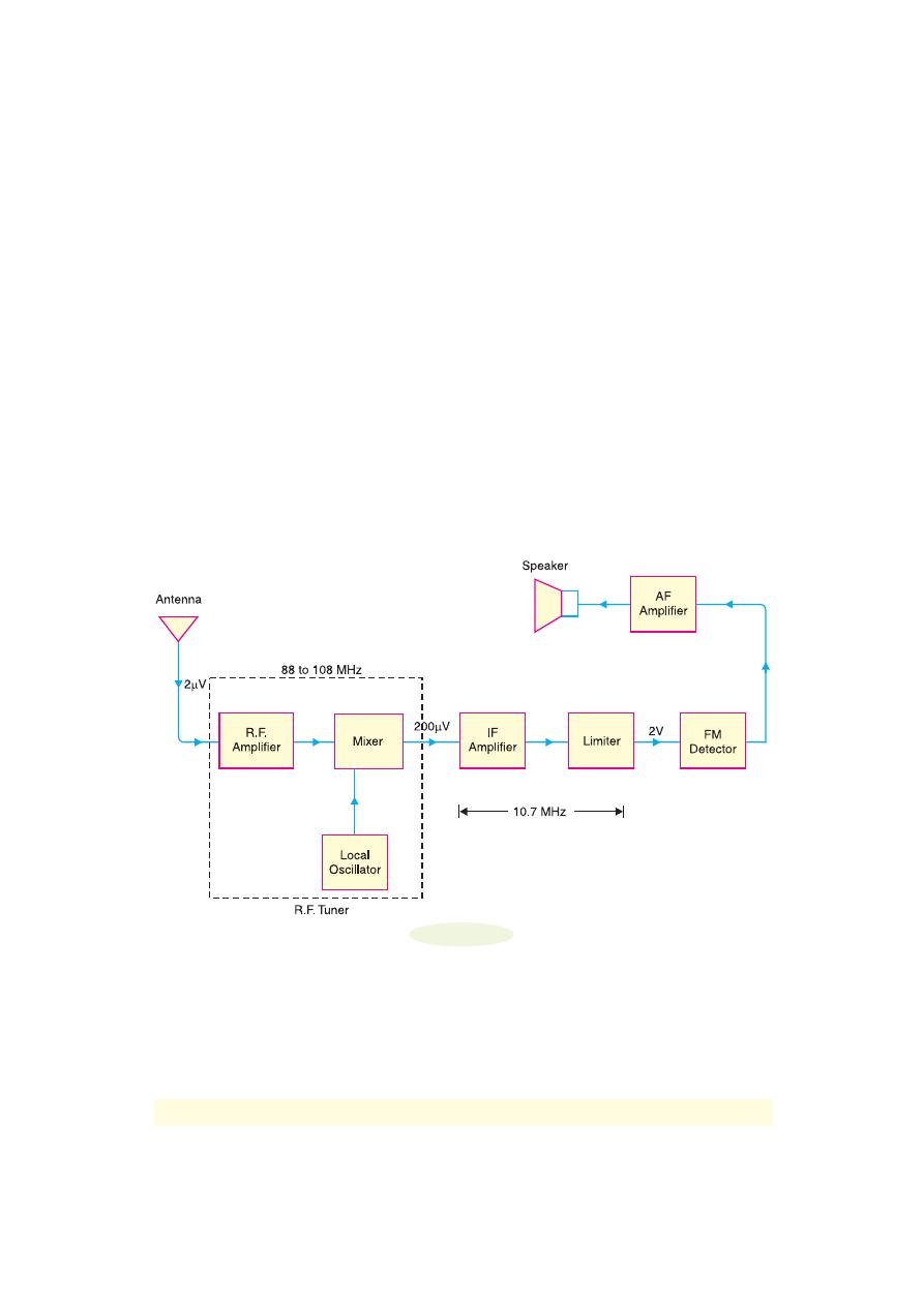
the block diagram of an FM receiver. In the interest of understanding, we shall discuss the various
sections of the FM receiver.
Fig. 16.21
1. R.F. Tuner.
The FM signals are in the frequency range of 88 to 108 MHz. The weak FM
signal (say 2
μV) is picked up by the antenna and is fed to the R.F. tuner. The R.F. tuner
consists of
(i)
R.F. amplifier
(ii)
Mixer and
(iii)
local oscillator. The R.F. amplifier amplifies
the selected FM signal (to 200
μV in the present case). The output from the RF amplifier is
fed to the mixer stage where it is combined with the output signal from a local oscillator. The
two frequencies beat together and produce an intermediate frequency (IF). The intermediate
frequency (IF) is equal to the difference between oscillator frequency and the RF frequency.
*
It is because the RF carrier frequencies for FM radio broadcasting are in the 88 to 108 MHz band.
○
○
○
○
○
○
○
○
○
○
○
○
○
○
○
○
○
○
○
○
○
○
○
○
○
○
○
○
○
○
○
○
○
○
○
○
○
○
○
○
○
○
○
○
○
○
○
○
○
○
Modulation And Demodulation
437
The IF is always 10.7 MHz (Recall IF in AM receiver is 455 kHz) regardless of the fre-
quency to which the FM receiver is tuned.
2. IF Amplifier Stage.
The output signal from the mixer always has a frequency of 10.7 MHz
and is fed to the IF amplifiers. Since IF amplifiers are tuned to IF (= 10.7 MHz), they render
nice amplification. Note that bandwidth of IF amplifiers is about 200 kHz or 0.2 MHz. The
IF gain is very large (assumed 10,000 in this case) so that output is 2V.
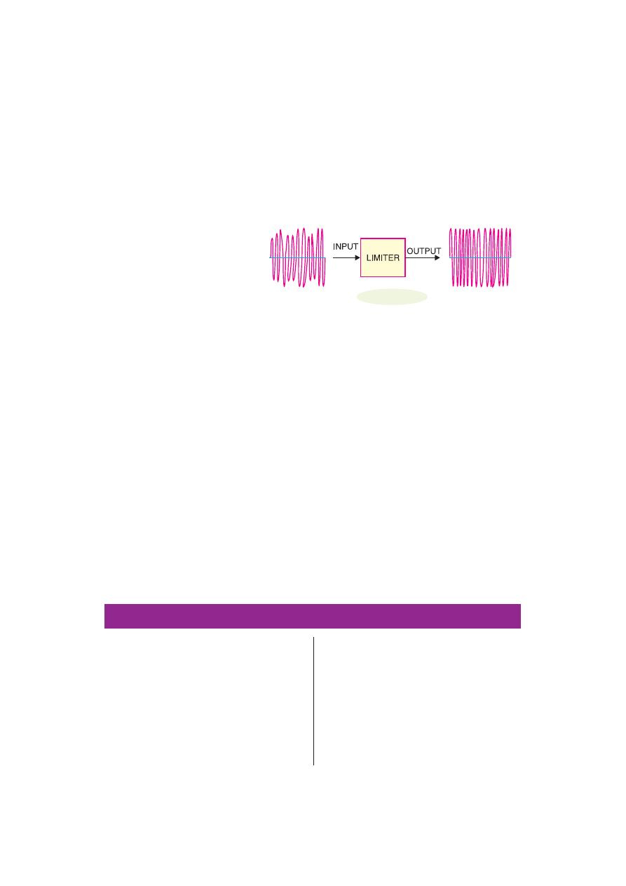
3. Limiter Stage.
The output
from IF stage is fed to the
limiter. This circuit is an IF
amplifier tuned to 10.7 MHz
but its main function is to re-
move AM interference from
the FM signal. Fig. 16.22
shows how the limiter re-
moves AM interference from the FM signal. The input is an FM signal, but it has different
amplitude levels because of AM interference has been added. However, the limiter circuit
keeps the output level constant for different input levels.
4. FM Detector.
After the removal of amplitude modulation from the FM signal by the limiter,
the IF signal drives the input of the FM detector. An FM detector is a circuit that converts
frequency variations to amplitude variations. The FM detector is also called a
discriminator
because it can distinguish between different frequencies in the input to provide different
output voltages. The resultant amplitude modulated signal is then rectified and amplified for
feeding to speaker for sound reproduction.
16.22 Difference Between FM and AM Receivers
Both FM and AM receivers employ superheterodyne principle. However, the following are the points
of differences between the two types of receivers :
(i)
An FM receiver has two additional stages viz. limiter and discriminator, which are quite
different from an AM receiver.
(ii)
FM broadcast signals lie in the frequency range between 88 and 108 MHz whereas AM
broadcast signals lie in the frequency range from 540 kHz to 1600 kHz.
(iii)
FM receivers are free from interference and this means that much weaker signals can be
successfully handled.
(iv)
FM bandwidth is about 200 kHz compared to 10 kHz bandwidth for AM.
(v)
The IF for FM receivers is 10.7 MHz whereas IF for AM receivers is 455 kHz.
MULTIPLE-CHOICE QUESTIONS
Fig. 16.22
1.
Modulation is done in .............
(i) transmitter
(ii) radio receiver
(iii) between transmitter and radio receiver
(iv) none of the above
2.
In a transmitter, ............. oscillator is used.
(i) Hartley
(ii) RC phase-shift
(iii) Wien-bridge
(iv) crystal
3.
In India, ............. modulation is used for ra-
dio transmission.
(i) frequency
(ii) amplitude
(iii) phase
(iv) none of the above
4.
In an AM wave, useful power is carried by
...........
(i) carrier
(ii) sidebands
(iii) both sidebands and carrier
(iv) none of the above
5.
In amplitude modulation, bandwidth is
............. the audio signal frequency.

438
Principles of Electronics
(i) thrice
(ii) four times
(iii) twice
(iv) none of the above
6.
In amplitude modulation, the ............. of car-
rier is varied according to the strength of the
signal.
(i) amplitude
(ii) frequency
(iii) phase
(iv) none of the above
7.
Overmodulation (amplitude) occurs when
signal amplitude is ............. carrier ampli-
tude.
(i) equal to
(ii) greater than
(iii) less than
(iv) none of the above
8.
In an AM wave, the majority of the power is
in .............
(i) lower sideband
(ii) upper sideband
(iii) carrier
(iv) none of the above
9.
At 100 % modulation, the power in each
sideband is ............. of that of carrier.
(i) 50 %
(ii) 40 %
(iii) 60 %
(iv) 25 %
10.
Overmodulation results in .............
(i) weakening of the signal
(ii) excessive carrier power
(iii) distortion
(iv) none of the above
11.
If modulation is 100 %, then signal ampli-
tude is ............. carrier amplitude.
(i) equal to
(ii) greater than
(iii) less than
(iv) none of the above
12.
As the modulation level is increased, the
carrier power .............
(i) is increased
(ii) remains the same
(iii) is decreased
(iv) none of the above
13.
Demodulation is done in .............
(i) receiving antenna
(ii) transmitter
(iii) radio receiver
(iv) transmitting antenna
14.
A high Q tuned circuit will permit an ampli-
fier to have high .............
(i) fidelity
(ii) frequency range
(iii) sensitivity
(iv) selectivity
15.
In radio transmission, the medium of trans-
mission is .............
(i) space
(ii) an antenna
(iii) cable
(iv) none of the above
16.
If level of modulation is increased .............
power is increased.
(i) carrier
(ii) sideband
(iii) carrier as well as sideband
(iv) none of the above
17.
In TV transmission, picture signal is .............
modulated.
(i) frequency
(ii) phase
(iii) amplitude
(iv) none of the above
18.
In a radio receiver, noise is generally devel-
oped at .............
(i) IF stage
(ii) receiving antenna
(iii) audio stage
(iv) RF stage
19.
Man made noises are ............. variations.
(i) amplitude
(ii) frequency
(iii) phase
(iv) both phase and frequency
20.
The signal voltage induced in the aerial of a
radio receiver is of the order of ..............
(i) mV
(ii)
μV
(iii) V
(iv) none of the above
21.
Superhetrodyne principle refers to .............
(i) using a large number of amplifier stages
(ii) using a push-pull circuit
(iii) obtaining lower fixed intermediate fre-
quency
(iv) none of the above
22.
If a radio receiver amplifies all the signal
frequencies equally well, it is said to have
high .............
(i) sensitivity
(ii) selectivity
(iii) distortion
(iv) fidelity
23.
Most of the amplification in a superhet-
rodyne receiver occurs at ............. stage.
(i) IF
(ii) RF amplifier
(iii) audio amplifier (iv) detector
24.
The letters AVC stand for .............
(i) audio voltage control
(ii) abrupt voltage control
(iii) automatic volume control
(iv) automatic voltage control
25.
The superhetrodyne principle provides se-
lectivity at ............. stage.
(i) RF
(ii) IF
(iii) audio
(iv) before RF
26.
In superhetrodyne receiver, the input at the
mixer stage is .............
(i) IF and RF
(ii) RF and AF
Modulation And Demodulation
439
(iii) IF and AF
(iv) RF and local oscillator signal
27.
The major advantage of FM over AM is
.............
(i) reception is less noisy
(ii) higher carrier frequency
(iii) smaller bandwidth
(iv) small frequency deviation
28.
When the modulating signal controls the fre-
quency of the carrier, we get, .............
(i) phase modulation
(ii) amplitude modulation
(iii) frequency modulation
(iv) may be any one of the above
29.
Modulation refers to a low-frequency sig-
nal controlling the .............
(i) amplitude of the carrier
(ii) frequency of the carrier
(iii) phase of the carrier
(iv) may be any of the above
30.
The IF is 455 kHz. If the radio receiver is
tuned to 855 kHz, the local oscillator fre-
quency is .............
(i) 455 kHz
(ii) 1310 kHz
(iii) 1500 kHz
(iv) 1520 kHz
31.
If A
min
= 40 and A
max
= 60, what is the per-
centage modulation ?
(i) 20 %
(ii) 40 %
(iii) 50 %
(iv)
10 %
32.
The function of ferrite antenna is to .............
(i) reduce stray capacitance
(ii) stabilise d.c. bias
(iii) increase the Q of tuned circuit
(iv) reduce noise
33.
In a radio receiver, we generally use .............
oscillator as a local oscillator.
(i) crystal
(ii) Wien-bridge
(iii) phase-shift
(iv) Hartley
34.
A 100 V carrier is made to vary between 160
V and 40 V by the signal. What is the modu-
lation factor ?
(i) 0.3
(ii) 0.6
(iii) 0.5
(iv) none of the above
35.
A 50 kW carrier is to be amplitude modu-
lated to a level of 85 %. What is the carrier
power after modulation ?
(i) 50 kW
(ii) 42.5 kW
(iii) 58.8 kW
(iv) 25 kW
36.
In the above question, what is the power in
sidebands ?
(i) 7.8 kW
(ii) 11.6 kW
(iii) 19.06 kW
(iv) 15.9 kW
37.
In a superhetrodyne receiver, the difference
frequency is chosen as the IF rather than the
sum frequency because ..............
(i) the difference frequency is closer to
oscillator frequency
(ii) lower frequencies are easier to amplify
(iii) only the difference frequency can be
modulated
(iv) none of the above
38.
The diode detector in an AM radio receiver
is usually found ..............
(i) before the first RF stage
(ii) after the first RF stage
(iii) after several stages of amplification
(iv) none of the above
39.
In a TRF radio receiver, the RF and detec-
tion stages are tuned to ..............
(i) radio frequency
(ii) IF
(iii) audio frequency
(iv) none of the above
40.
In TV transmission, sound signal is ..............
modulated
(i) amplitude
(ii) frequency
(iii) phase
(iv) none of the above
Answers to Multiple-Choice Questions
1.
(i)
2.
(iv)
3.
(ii)
4.
(ii)
5.
(iii)
6.
(i)
7.
(ii)
8.
(iii)
9.
(iv)
10.
(iii)
11.
(i)
12.
(ii)
13.
(iii)
14.
(iv)
15.
(i)
16.
(ii)
17.
(iii)
18.
(iv)
19.
(i)
20.
(ii)
21.
(iii)
22.
(iv)
23.
(i)
24.
(iii)
25.
(ii)
26.
(iv)
27.
(i)
28.
(iii)
29.
(iv)
30.
(ii)
31.
(i)
32.
(iii)
33.
(iv)
34.
(ii)
35.
(i)
36.
(iii)
37.
(ii)
38.
(iii)
39.
(i)
40.
(ii)

440
Principles of Electronics
Chapter Review Topics
1.
Explain the general principles of radio broadcasting, transmission and reception.
2.
What is modulation ? Why is modulation necessary in communication system ?
3.
Explain amplitude modulation. Derive the voltage equation of an AM wave.
4.
What do you understand by modulation factor ? What is its significance ?
5.
Draw the waveform of AM wave for the following values of modulation factor :
(i) 0
(ii) 0.5
(iii) 1
(iv) 1.5
6.
What do you understand by sideband frequencies in an AM wave ?
7.
Derive an expression for the fraction of total power carried by the sidebands in amplitude modulation.
8.
What are the limitations of amplitude modulation ?
9.
What do you understand by frequency modulation ? Explain its advantages over amplitude modula-
tion.
10.
What is demodulation ? What are essentials in demodulation ?
11.
Draw the diode detector circuit and explain its action.
12.
What is superhetrodyne principle ? Explain the function of each stage of superhetrodyne receiver with
the help of a block diagram.
Problems
1.
The maximum peak-to-peak voltage of an AM wave is 16 mV while the minimum peak-to-peak
voltage is 8 mV. Find the percentage modulation.
[60%]
2.
A carrier of peak voltage 0.05 V and frequency 200 kHz is amplitude modulated by a signal of peak
voltage 10 V and frequency 1 kHz. Find (i) frequencies in the output spectrum and (ii) the peak values
of output components if m = 0.5 and voltage gain A = 100.
[(i) 199 kHz, 200 kHz, 201 kHz (ii) 1.25 V, 5 V, 1.25 V
]
3.
An AM transmitter supplies 10kW to the antenna when unmodulated. Determine the total power
radiated by the transmitter when modulated to 30%.
[10.45 kW]
4.
A certain AM transmitter radiates 8kW with carrier unmodulated and 9kW when the carrier is modu-
lated. Find the percentage modulation.
[50%]
5.
A transmitter radiates a total power of 10 kW. The carrier is modulated to a depth of 60% . Calculate
(i) the power in the carrier and (ii) power in each sideband.
[(i) 8.47kW (ii) 0.765kW]
6.
A carrier of 100 V and 1500 kHz is modulated by 60V, 1200 Hz sinusoidal signal. Calculate modu-
lation factor and express this as percentage.
[0.6; 60%]
7.
A carrier with an amplitude of 140 V is modulated by a signal with an amplitude of 80V. What is the
percentage modulation ? What is the amplitude of lower sideband frequency ?
[57% ; 40V]
8.
A 50 kW carrier is to be modulated to a level of 85%. What is the carrier power after modulation ?
What is sideband power ?
[50 kW ; 19.06 kW]
9.
The r.m.s. antenna current of a radio transmitter is 10 A when unmodulated, rising to 12 A when the
carrier is sinusoidally modulated. What is the modulation index ?
[0.94]
10.
The r.m.s. antenna current of an AM transmitter increases by 15% over the unmodulated value when
sinusoidal modulation is applied. Determine the modulation index.
[0.8]
11.
A 500 Hz modulating voltage produces a frequency deviation of 2.25 kHz. What is the modulation
index ? If the amplitude of the modulation voltage is kept constant, but its frequency is raised to
6 kHz, what is the new deviation ?
[4.5 ; 54 kHz]
12.
When the modulating frequency in an FM system is 400 Hz and the modulation voltage is 2.4V, the
modulation index is 60. Calculate the maximum deviation. What is the modulation index when the
modulating frequency is reduced to 250 Hz and the modulating voltage is simultaneously raised to
3.2V ?
[24 kHz ; 128]

Modulation And Demodulation
441
Discussion Questions
1.
Why cannot electrical energy be radiated at low frequencies (< 20 kHz) ?
2.
Why is radio transmission carried at high frequencies ?
3.
Why does amplitude modulation give noisy reception ?
4.
Why do we always design the oscillator to produce a frequency of 455 kHz above and not below the
incoming radio wave ?
5.
What is the importance of modulation factor in communication system ?
6.
Why is superhetrodyne principle employed in radio receivers ?
7.
Why is AM and not FM employed for radio transmission in India ?
8.
Why does frequency modulation give noiseless reception ?
9.
Why have we selected IF as 455 kHz ?
10.
What is the importance of sideband frequencies ?