Electrical Machines Lab
Experiment-No. five
Date: 13-12-2016
Starting Methods of DC Separately Exited Motor
AIME : To reduce the armature current in DC separately exited by using a
gradually decreasing tapped resistance between the supply voltage and the motor
armature .
THEORY:
It is well known that when starting a DC separately exited motor and that is by
connecting its armature circuit directly to a DC voltage source
، a high value of the
armature current is expected. Such high value is primarily due to the lack of the
back electromotive force (emf) of the motor. The back electromotive force is
known to be proportional to the motor speed. The high value of the armature
current may cause troubles to the DC motor like reduction of its life time, creation
of false operation of
the protective devices associated with the motor, etc…).
One of the classical remedies to such problem is to insert a starting resistor in
series with the motor armature circuit.
The starting resistor should be gradually removed as the motor speeds up.
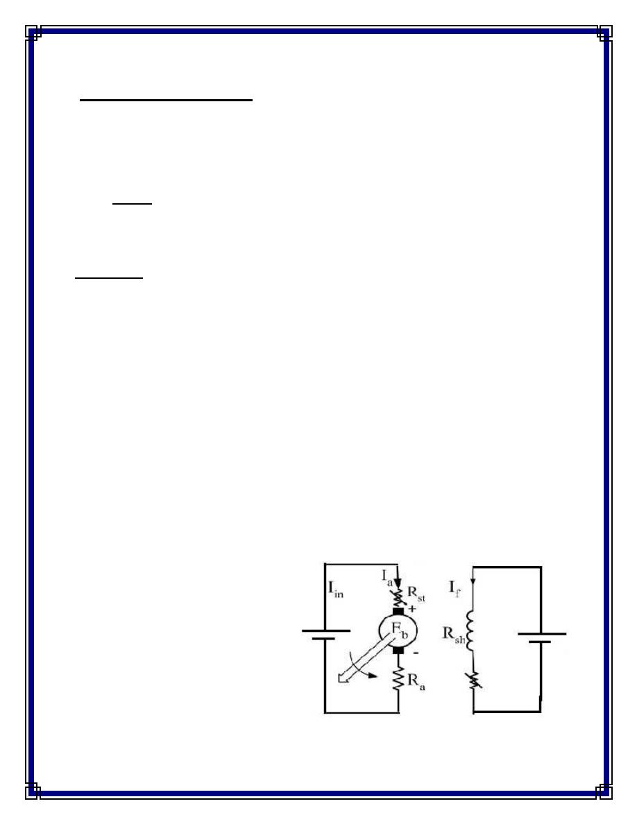
Circuit Diagram
:-
Fig.(1)
DC separately exited
motor
V
f
V
a
Working Principle :-
A variable resistance is connected in series with armature and the field winding
is connected directly with separate source. The parameters of DC separately exited
motors are:-
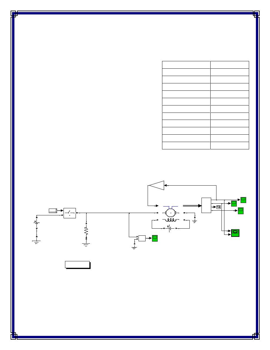
Case 1: DC Separately Exited Motor Without Starter
Initially, the back emf produced at the armature is zero. After full voltage is supplied across the
armature, a very high current is obtained (I
a
= 316A) since the value of armature resistance is low.
Parameters
values
R
a
0.6
Ω
L
a
0.012H
R
f
240
Ω
L
f
120H
L
af
1.8H
J
1 Kg m
2
B
m
0 Nms
T
f
0 Nm
Initial speed
1 rad/sec
Rated current
11.78A
Rated Power
5 HP
Fig.(2) Parameter of motor
DC Motor
Torque is proportional to speed; TL=Bl*w
w(rad\s) versus Ia (A)
w
Continuous
Va_
v
+
-
Va
Timer
Te
g
1
2
Ideal Switch
Ia
Ef=240 V
E
240 V
Demux
m
A+
F+
A-
F-
dc
TL
DC_Motor
5 hp; 240V; 16.2 A; 1220rpm
0.2287
BL
10 kohm
Fig.(3) Starting motor without starter
2
Out
1
In
x ohm
t ohm
p ohm
b ohm
a ohm
c
1
2
Breaker4
c
1
2
Breaker3
c
1
2
Breaker2
c
1
2
Breaker1
c
1
2
Breaker
8.8
6.8
4.8 s
2.8 s
10.8
The fuses will blow out due to this excess current and the brushes and commutators will also get
damaged.
To avoid damaging effect of high initial current, we will insert resistances in series with the armature
(for certain time interval) which brings the initial current to safe value. The starter resistances are
gradually shorted by the circuit breaker. The motor develops speed and back emf till it attains its rated
values.
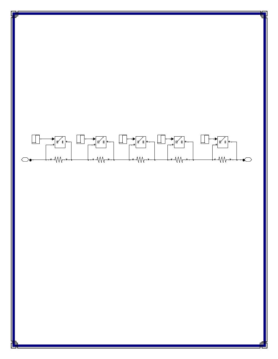
Case 2: : DC Separately Exited Motor With Starter
A Five step starter system is designed for limiting the starting armature current to a low
value and then gradually decreasing the resistances to finally the armature resistance.
The motor then attains its rated current and operates normally. The role of starter thus
gets over.
Initially, now starting armature current I
a
= V/R
1
; which comes out to be very less. Let
the values of each resistance of the starter be a, b, and c ohms.
Therefore
R
1
= a + b +p +x +t +R
a
R
2
= b +p +x +t +R
a
R
3
= p +x +t +R
a
R
4
= x +t +R
a
R
3
= t +R
a
The values of a, b, p, x, t can be found out from the relation
I
1
/I
2
=R
1
/R
2
=R
2
/R
3
=R
3
/R
a
=k ……………(1)
Fig.(4) starter circuit
Starting a DC Motor
Torque is proportional to speed; TL=Bl*w
w(rad\s) versus Ia (A)
w
Continuous
Va_
v
+
-
Va
Timer
Te
In
Out
5 step
starter
Motor Starter
?
More Info
g
1
2
Ideal Switch
Ia
Ef=240 V
E
240 V
Demux
m
A+
F+
A-
F-
dc
TL
DC_Motor
5 hp; 240V; 16.2 A; 1220rpm
0.2287
BL
10 kohm
Suppose we want to limit the upper limit of current to twice the value of lower limit
current (or rated current), then we have k= 2, so from equation (1), we first solve the
equation R
5
/R
a
= 2. Putting R
a
=0.61 and R
5
= 0.61+t,
we get t=0.61ohm.
Similarly by solving all the other equations we get the values of x=1.22 ohm, p= 2.44
ohm, b= 4.88 ohm and a=9.76 ohm.
Hence we get the values of R
1
= 19.52 ohm, R
2
=9.76 ohm ,R
3
= 4.88 ohm, R
4
=2.44 ohm,
R
5
= 1.22 ohm.
Hence initial current comes out to be
I
a
= 230/19.52 =11.78 A
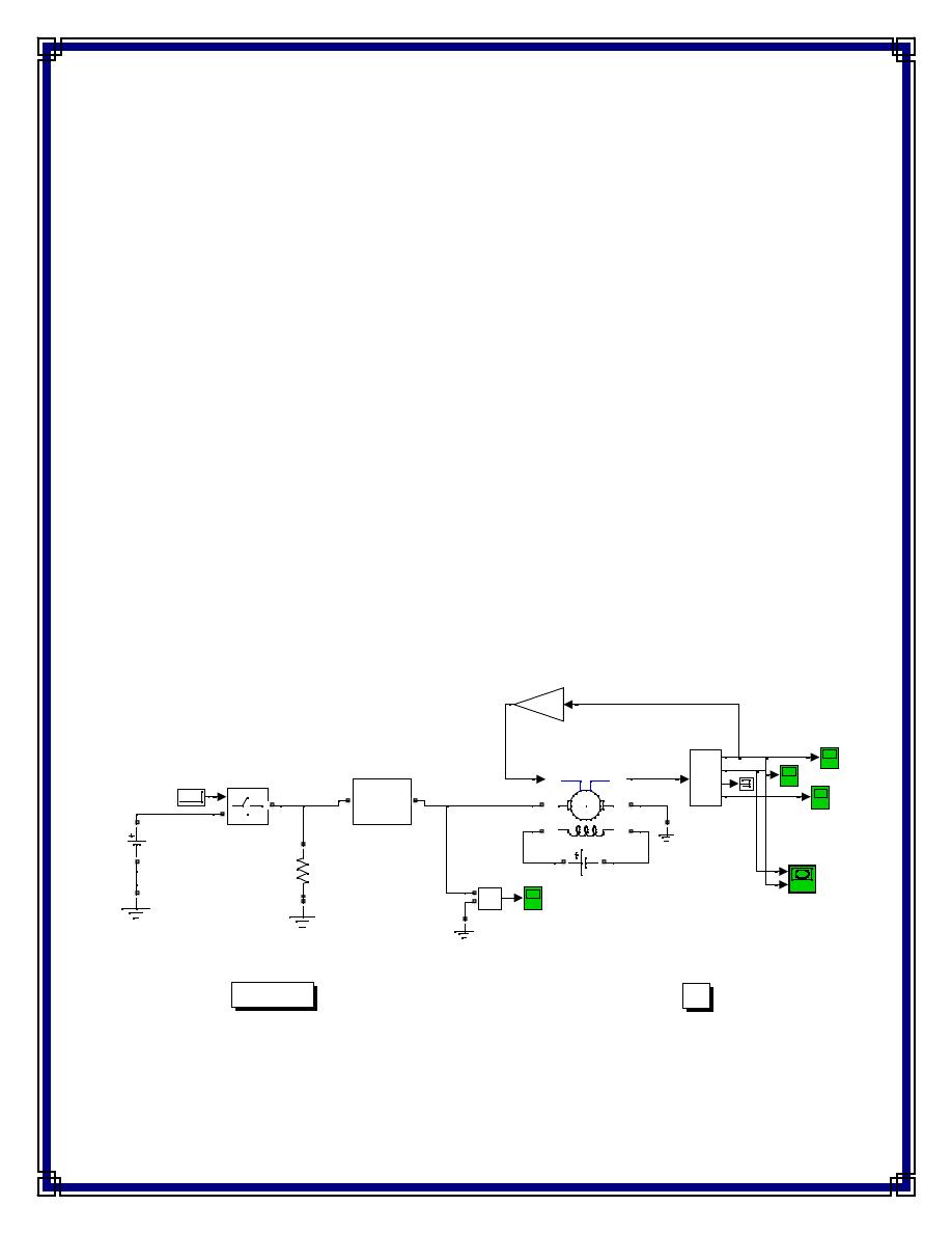
After 2.8 seconds, the res
istance ‘a’ gets shorted by the circuit breaker placed in
parall
el with the resistance ‘a’. The current then falls down to a certain value .The
value of the next current will now depend not only on
the starter resistance R
2
but also speed and back emf developed in the armature
resistance. Finally after 10.8 seconds the role of the starter gets over and the motor
begins to operate at its rated current, I=11.78A.
Fig.(5) Starting motor with starter

PROCEDURES:
1- Open File ---> New---> Model.
2- Open Simulink Library and browse the components.
3- Select DC Machine ratings 5hp ,240v, 16.2A, 1220 rpm.
4- Connect the components as shown in fig. (3).
5- Plot the armature current, armature voltage, speed and the torque.
6- Connect the components as shown in fig. (5).
7- Plot the armature current, armature voltage, speed and the torque.
Report:
1. Compare between the results of step No. (5) and No.(7) in procedures.
2. What is the benefits of starter.
3. If k=1.5 find the step resistance .