
DC Chopper Circuits
Prof. Dr Basil M. Saied
2016-2017
1
DC-DC Converters

2
DC-DC Converters
•
Convert a fixed DC Source into a Variable DC
Source
•
DC equivalent to an AC transformer with
variable turns ratio
•
Step-up and Step-down versions
•
Applications
▫
Motor Control
▫
Voltage Regulators
2
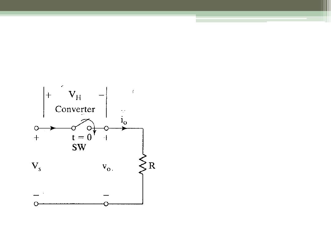
Step-down Operation
Switch SW is known as
a “Chopper”
Use BJT, MOSFET, or
IGBT
Close for time t
1
V
S
appears across R
Open for time t
2
Voltage across R = 0
Repeat
Period T = t
1
+ t
2
3
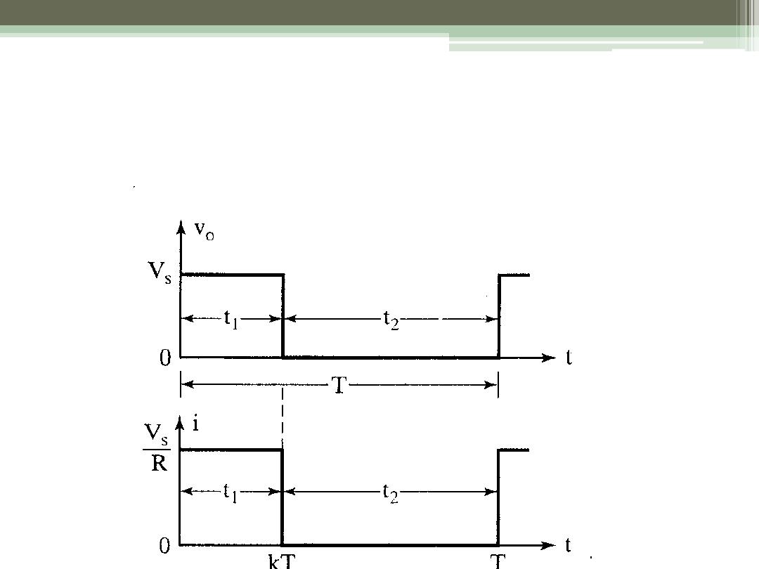
Waveforms for the Step-Down Converter
4
Average Value of the Load Current
1
a
S
a
V
kV
I
R
R
T
period
t
k
dutycycle
T
f
frequency
5
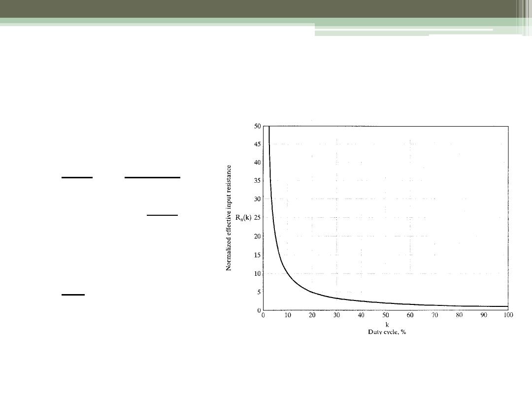
Effective Input Resistance seen by V
S
6
S
S
i
S
a
i
V
V
R
V
I
k
R
R
R
k

Modes of Operation
•
Constant – frequency operation
▫
Period T held constant, t
1
varied
▫
Width of the pulse changes
▫
“Pulse-width Control”, PWC
•
Variable -- frequency operation
▫
Change the chopping frequency (period T)
▫
Either t
1
or t
2
is kept constant
▫
“Frequency Control” FC
ECE 442 Power
Electronics
7
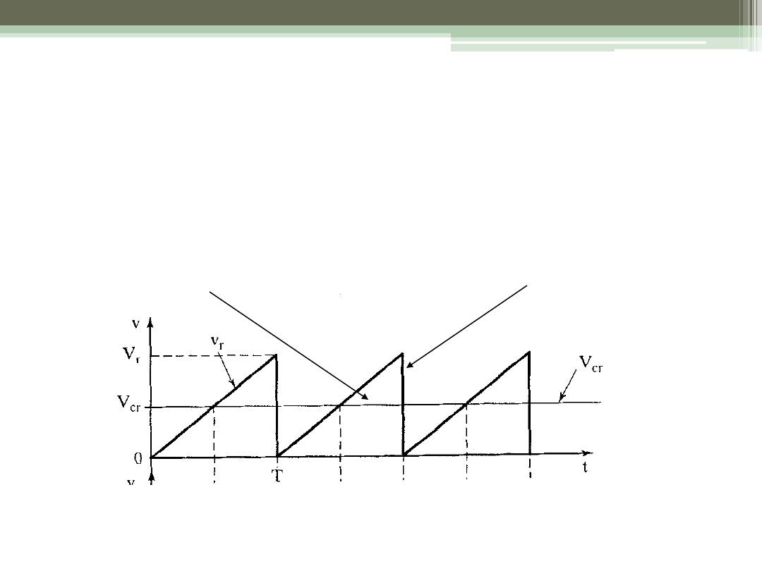
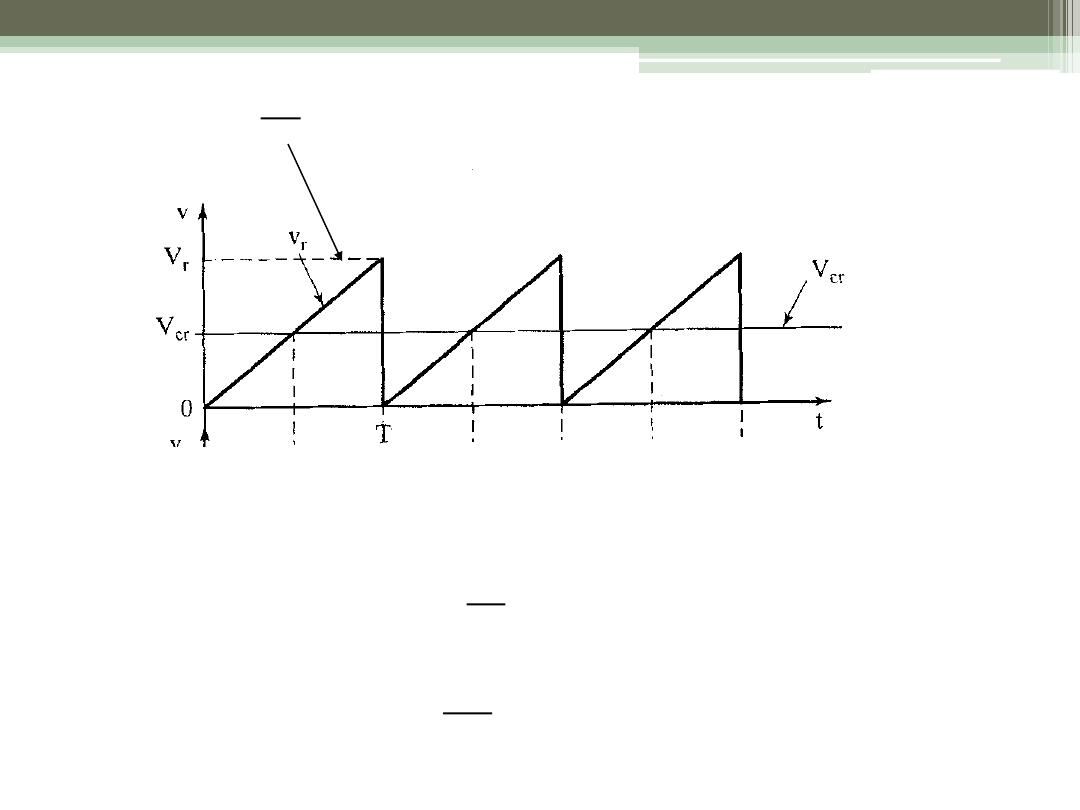
Generation of Duty Cycle
•
Compare a dc reference signal with a saw-tooth
carrier signal
ECE 442 Power
Electronics
8
DC Reference Signal
Carrier Signal
9
r
r
V
v
k
T
@
r
cr
r
cr
cr
r
v
V
t
kT
V
V
kT
T
V
k
M
V
kT
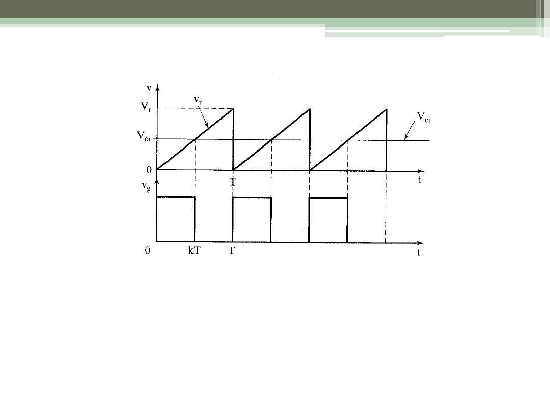
To generate the gating signal
•
Generate the triangular waveform of period T, v
r
,
and the dc carrier signal, v
cr
•
Compare to generate the difference v
c
- v
cr
•
Apply to a “hard limiter” to “square off”
10
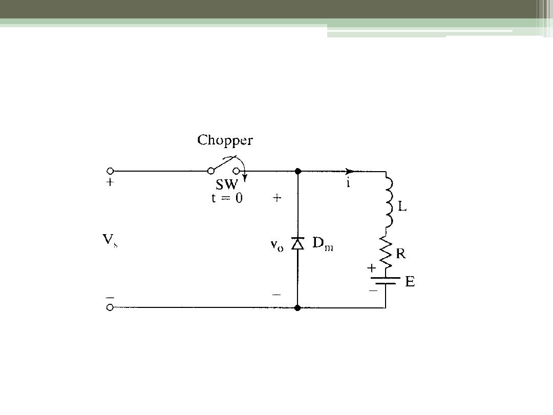
Step-Down Converter with RL Load
ECE 442 Power
Electronics
11
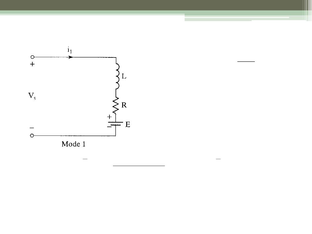
Mode 1: Switch Closed
1
1
2
(
)
t
t
kT
i kT
I
1
1
S
di
V
Ri
L
E
dt
1
1
( )
1
R
R
t
t
L
L
S
V
E
i t
I e
e
R
1
(
)
t
t kT
12
1
(
0 )
1
( )
t
i t
I
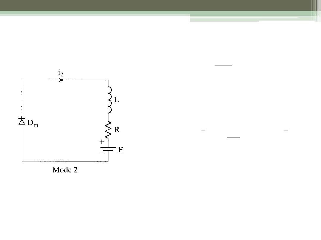
Mode 2: Switch Open
2
2
2
2
2
2
0
(
0)
( )
1
R
R
t
t
L
L
di
Ri
L
E
dt
i t
I
E
i t
I e
e
R
2
2
2
2
3
1
0
(1
)
@
(1
)
( )
t
t
k T
t
t
K T
i t
I
I
ECE 442 Power
Electronics
13
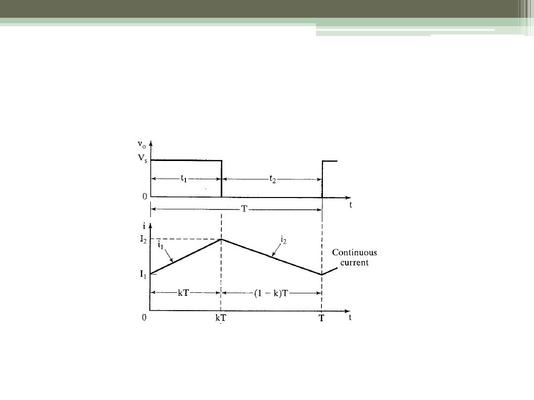
Current for “Continuous” Mode
ECE 442 Power
Electronics
14

15
1
2
( 1
)
max
1
1
1
1
1
1
4
kz
S
z
kz
S
z
kz
z
k z
S
z
S
V e
E
I
R e
R
V e
E
I
R e
R
T R
z
L
V
e
e
e
I
R
e
V
I
fL

For Continuous Current
ECE 442 Power
Electronics
16
1
0
1
0
1
kz
z
S
I
e
E
e
V

Define the load emf ratio
1
1
S
kz
z
S
E
x
V
E
e
x
V
e
ECE 442 Power
Electronics
17
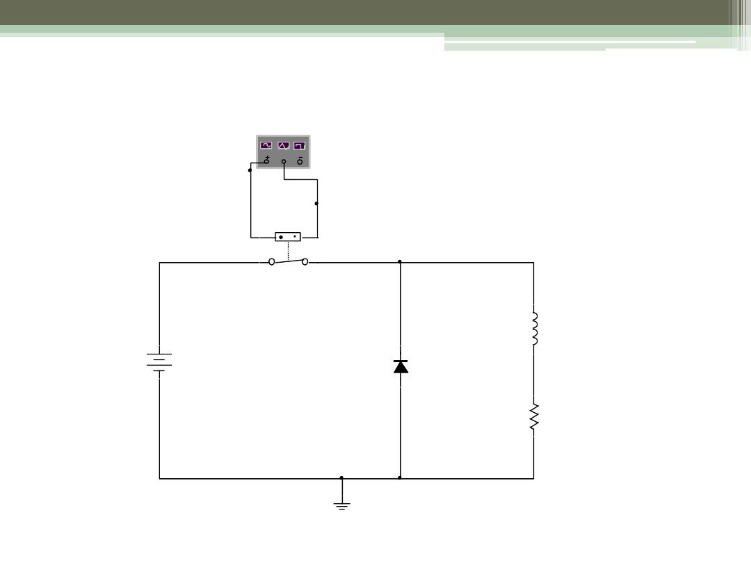
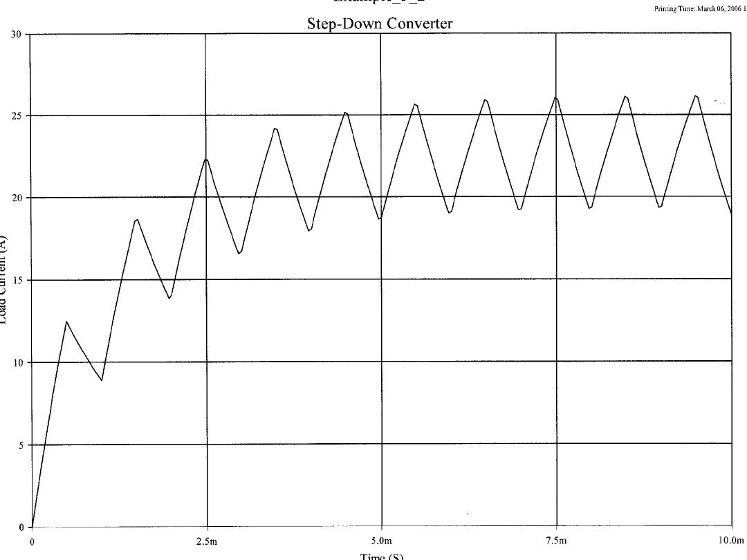
Example 5.2
18
Vs
220V
J1
1V 0V
XFG1
L
7.5mH
R
5ohm
D 2
D IOD E_VIR TUAL
ECE 442 Power
Electronics
19
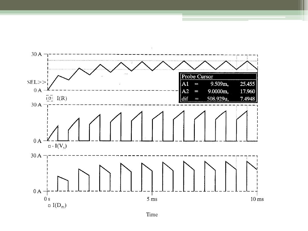
SPICE Results
ECE 442 Power
Electronics
20