
C O N T E N T S
1. OILWELL CEMENTS
1.1 Functions of oilwell cement
1.2 Classification of cement powders
1.3 Mixwater Requirements
2. PROPERTIES OF CEMENT
3. CEMENT ADDITIVES
4. PRIMARY CEMENTING
4.1 Downhole cementing equipment
4.2 Surface cementing equipment
4.3 Single Stage Cementing Operation
4.4 Multi - Stage cementing Operation
4.5 Inner string cementing
4.6 Liner cementing
4.7 Recommendations for a good cement job
5. SQUEEZE CEMENTING
5.1 High Pressure Squeeze
5.2 Low pressure squeeze
5.3 Equipment used for squeeze cementing
5.4 Testing the squeeze job
6. CEMENT PLUGS
7. EVALUATION OF CEMENT JOBS
Cementing

LEarNiNg OBJECTiVES :
Having worked through this chapter the student will be able to:
General
• Describe the principal functions of cement.
Cement Slurries
• List and describe the major properties of a cement slurry.
• Describe the additives used in cement slurries and the way in which they affect
the properties of the slurry.
Cementing Operations
• Calculate the volume of : slurry, cement, mixwater, displacing fluid required for
a single stage and two-stage cementing operation.
• Calculate the bottomhole pressures generated during the above cementing
operations.
• Describe the surface and downhole equipment used in a single, two-stage and
liner cementation operation.
• Prepare a program for a single and two stage cementing operation and describe
the ways in which a good cement bond can be achieved.
Cement Plugs
• Describe the reasons for setting cement plugs.
• Describe the principal methods for placing a cement plug in casing or open
hole.
• Calculate the displacement volumes for an underbalanced cement plug.
Evaluation of Cementing Operations
• Describe the principles involved and the tools and techniques used to evaluate
the quality of a cementing operation.
• Discuss the limitations of the above techniques.
Cementing
Institute of Petroleum Engineering, Heriot-Watt University
1. iNTrOduCTiON
Cement is used primarily as an impermeable seal material in oil and gas well
drilling. It is most widely used as a seal between casing and the borehole, bonding
the casing to the formation and providing a barrier to the flow of fluids from, or into,
the formations behind the casing and from, and into, the subsequent hole section
(Figure 1). Cement is also used for remedial or repair work on producing wells.
It is used for instance to seal off perforated casing when a producing zone starts
to produce large amounts of water and/or to repair casing leaks. This chapter will
present: the reasons for using cement in oil and gas well drilling; the design of the
cement slurry; and the operations involved in the placement of the cement slurry.
The methods used to determine if the cementing operation has been successful will
also be discussed.
1.1 Functions of oilwell cement
There are many reasons for using cement in oil and gaswell operations. As stated
above, cement is most widely used as a seal between casing and the borehole,
bonding the casing to the formation and providing a barrier to the flow of fluids
from, or into, the formations behind the casing and from, and into, the subsequent
hole section (Figure 1). However, when placed between the casing and borehole the
cement may be required to perform some other tasks. The most important functions
of a cement sheath between the casing and borehole are:
• To prevent the movement of fluids from one formation to another or from the
formations to surface through the annulus between the casing and borehole.
• To support the casing string (specifically surface casing)
• To protect the casing from corrosive fluids in the formations.
However, the prevention of fluid migration is by far the most important function
of the cement sheath between the casing and borehole. Cement is only required
to support the casing in the case of the surface casing where the axial loads on
the casing, due to the weight of the wellhead and BOP connected to the top of
the casing string, are extremely high. The cement sheath in this case prevents the
casing from buckling.
The techniques used to place the cement in the annular space will be discussed
in detail later but basically the method of doing this is to pump cement down the
inside of the casing and through the casing shoe into the annulus (Figure 2). This
operation is known as a primary cement job. A successful primary cement job is
essential to allow further drilling and production operations to proceed.
Conductor pipe
Surface casing
Cement
Perforations
Production casing
Intermediate casing
Production tubing
Liner
Normally pressured
Abnormally pressured
Figure 1
Functions of Primary Cementing
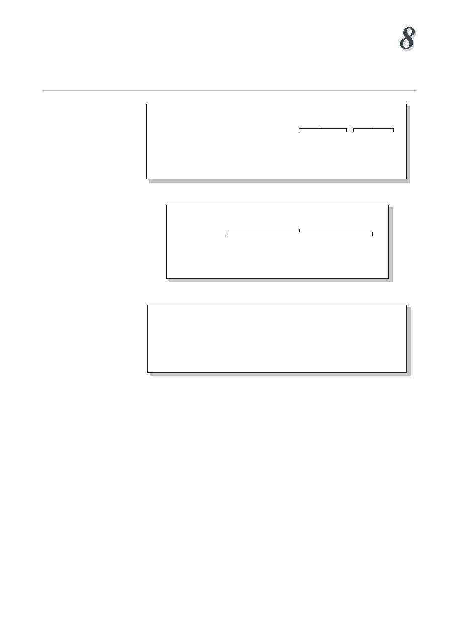
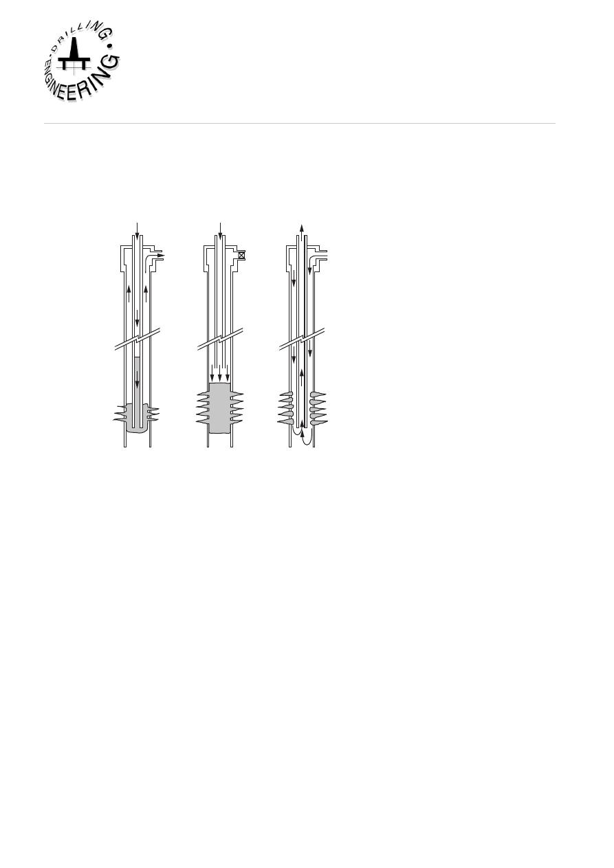
Circulating
mud
Pumping spacer
and slurry
Displacing
Displacing
End of job
Top
cementing
plug
Bottom
cementing
plug
Centralizers
Float
collar
Shoe
Spacer
Slurry
Displacing
Fluid
Original
mud
Plug release pin in
Plug release pin out
Figure 2
Primary Cementing Operations
Cementing
Institute of Petroleum Engineering, Heriot-Watt University
Spot cement Apply squeeze Reverse circulate
pressure
Schematic of Bradenhead squeeze technique normally used on low pressure
formations. Cement is circulated into place down drill pipe (left), then the wellhead,
or BOP, is closed (centre) and squeeze pressure is applied. Reverse circulating
through perforations (right) removes excess cement, or the plug can be drilled out.
Figure 3
Secondary or Squeeze Cementing Operation
Another type of cement job that is performed in oil and gas well operations is called
a secondary or squeeze cement job. This type of cement job may have to
be done at a later stage in the life of the well. A secondary cement job may be
performed for many reasons, but is usually carried out on wells which have been
producing for some time. They are generally part of remedial work on the well
(e.g. sealing off water producing zones or repairing casing leaks). These cement
jobs are often called squeeze cement jobs because they involve cement being forced
through holes or perforations in the casing into the annulus and/or the formation
(Figure 3).
The specific properties of the cement slurry which is used in the primary and
secondary cementing operations discussed above will depend on the particular
reason for using the cement (e.g. to plug off the entire wellbore or simply to plug
off perforations) and the conditions under which it will be used (e.g. the pressure
and temperature at the bottom of the well).
The cement slurry which is used in the above operations is made up from: cement
powder; water; and chemical additives. There are many different grades of cement
powder manufactured and each has particular attributes which make it suitable for
a particular type of operation. These grades of cement powder will be discussed
below. The water used may be fresh or salt water. The chemical additives (Figure
4) which are mixed into the cement slurry alter the properties of both the cement
slurry and the hardened cement and will be discussed at length in Section 3 below.
CEMENT SLURRY
Retarders;
Calcium lignosulphonate
CMHEC
Saturated salt solution
Extenders;
Bentonite
Pozzolan
Fluid loss additives;
Organic polymers
CMHEC
Mud contaminants;
Diesel
NaOH
Accelerators;
CaCI2
NaCI
Heavy weight material;
Barite
Haemitite
Friction reducers (dispersants);
Polymers
Calcium ligno sulphonate
Figure 4
Major cement additives
API Class
C3S
C2S C3A C4AF CaSO4
SQq. cm/Gram
A
53
24
8
8
3.5
1600-1900
B
44
32
5
12
2.9
1500-1900
C
58
16
8
8
4.1
2000-2400
D&E
50
26
5
13
3
1200-1500
G
52
27
3
12
3.2
1400-1600
H
52
25
5
12
3.3
1400-1600
*Plus free lime, alkali, (Na, K, Mg)
Compounds*
Fineness
Table 1
Composition of API Cements
Each cement job must be carefully planned to ensure that the correct cement and
additives are being used, and that a suitable placement technique is being employed
for that particular application. In planning the cement job the engineer must ensure
that:
• The cement can be placed correctly using the equipment available
• The cement will achieve adequate compressive strength soon after it is placed
• The cement will thereafter isolate zones and support the casing throughout the
life of the well
To assist the engineer in designing the cement slurry, the cement slurry is tested
in the laboratory under the conditions to which it will be exposed in he wellbore.
Theses tests are known as pilot tests and are carried out before the job goes ahead.
These tests must simulate downhole conditions as closely as possible. They will
Cementing
Institute of Petroleum Engineering, Heriot-Watt University
help to assess the effect of different amounts of additives on the properties of the
cement (e.g. thickening time, compressive strength development etc).
API Class
Mixwater
Slurry Weight
Gals/Sk.
Lbs/Gal.
A
5.2
15.6
B
5.2
15.6
C
6.3
14.8
D
4.3
16.4
E
4.3
16.4
F
4.3
16.2
G
5.0
15.8
H
4.3
16.4
Table 2
API Mixwater requirements for API cements
1.2 Classification of cement powders
There are several classes of cement powder which are approved for oilwell drilling
applications, by the American Petroleum Institute - API. Each of these cement
powders have different properties when mixed with water. The difference in
properties produced by the cement powders is caused by the differences in the
distribution of the four basic compounds which are used to make cement powder;
C
3
S, C
2
S, C
3
A, C
4
AF (Table 1).
Classes A and B
- These cements are generally cheaper than other classes of cement
and can only be used at shallow depths ,where there are no special requirements.
Class B has a higher resistance to sulphate than Class A.
Class C
- This cement has a high C
3
S content and therefore becomes hard relatively
quickly.
Classes D,E and F
- These are known as retarded cements since they take a much
longer time to set hard than the other classes of cement powder. This retardation is
due to a coarser grind. These cement powders are however more expensive than the
other classes of cement and their increased cost must be justified by their ability to
work satisfactorily in deep wells at higher temperatures and pressures.
Class G and H
- These are general purpose cement powders which are compatible
with most additives and can be used over a wide range of temperature and pressure.
Class G is the most common type of cement and is used in most areas . Class H has
a coarser grind than Class G and gives better retarding properties in deeper wells.
There are other, non-API, terms used to classify cement. These include the
following:
• Pozmix cement - This is formed by mixing Portland cement with pozzolan
(ground volcanic ash) and 2% bentonite. This is a very lightweight but durable
cement. Pozmix cement is less expensive than most other types of cement and due
to its light weight is often used for shallow well casing cementation operations.
Portland
API Class G
API ClassH
Water,
5.19
4.97
4.29
gal./sk.
Slurry Wt.
15.9
15.8
16.5
lb./gal.
Slurry Vol.
1.8
1.14
1.05
cuft./sk.
Temp. (deg. F) Pressure (psi) Typical comp. strength (psi) @ 12hrs
60
0
615
440
325
80
0
1470
1185
1065
95
800
2085
2540
2110
110
1600
2925
2915
2525
140
3000
5050
4200
3160
170
3000
5920
4380
4485
200
3000
-
5110
4575
Typical comp. strength (psi) @ 24hrs
60
0
2870
-
-
80
0
4130
-
-
95
800
4130
-
-
110
1600
5840
-
-
140
3000
6550
-
7125
170
3000
6210
5865
7310
200
3000
-
7360
9900
Table 3
Compressive strength of cements
• Gypsum Cement - This type of cement is formed by mixing Portland cement
with gypsum. These cements develop a high early strength and can be used for
remedial work. They expand on setting and deteriorate in the presence of water and
are therefore useful for sealing off lost circulation zones.
• Diesel oil cement - This is a mixture of one of the basic cement classes (A, B, G,
H ), diesel oil or kerosene and a surfactant. These cements have unlimited setting
times and will only set in the presence of water. Consequently they are often used
to seal off water producing zones, where they absorb and set to form a dense hard
cement.
1.3 Mixwater Requirements
The water which is used to make up the cement slurry is known as the mixwater.
The amount of mixwater used to make up the cement slurry is shown in Table 2.
These amounts are based on :
• The need to have a slurry that is easily pumped.
• The need to hydrate all of the cement powder so that a high quality hardened
cement is produced.
• The need to ensure that all of the free water is used to hydrate the cement
powder and that no free water is present in the hardened cement.
Cementing
Institute of Petroleum Engineering, Heriot-Watt University
The amount of mixwater that is used to make up the cement slurry is carefully
controlled. If too much mixwater is used the cement will not set into a strong,
impermeable cement barrier. If not enough mixwater is used :
• The slurry density and viscosity will increase.
• The pumpability will decrease
• Less volume of slurry will be obtained from each sack of cement
The quantities of mixwater quoted in Table 2 are average values for the different
classes of cement. Sometimes the amount of mixwater used will be changed to
meet the specific temperature and pressure conditions which will be experienced
during the cement job.
2. PrOPErTiES OF CEMENT
The properties of a specific cement slurry will depend on the particular reason for
using the cement, as discussed above. However, there are fundamental properties
which must be considered when designing any cement slurry.
(a) Compressive strength
The casing shoe should not be drilled out until the cement sheath has reached a
compressive strength of about 500 psi. This is generally considered to be enough
to support a casing string and to allow drilling to proceed without the hardened
cement sheath, disintegrating, due to vibration. If the operation is delayed whilst
waiting on the cement to set and develop this compressive strength the drilling rig
is said to be “waiting on cement” (WOC). The development of compressive
strength is a function of several variables, such as: temperature; pressure; amount
of mixwater added; and elapsed time since mixing.
The setting time of a cement slurry can be controlled with chemical additives, known
as accelerators. Table 3 shows the compressive strengths for different cements
under varying conditions.
(b) Thickening time (pumpability)
The thickening time of a cement slurry is the time during which the cement slurry
can be pumped and displaced into the annulus (i.e. the slurry is pumpable during
this time). The slurry should have sufficient thickening time to allow it to be:
• Mixed
• Pumped into the casing
• Displaced by drilling fluid until it is in the required place
Generally 2 - 3 hours thickening time is enough to allow the above operations to
be completed. This also allows enough time for any delays and interruptions in the
cementing operation. The thickening time that is required for a particular operation
will be carefully selected so that the following operational issues are satisfied:
• The cement slurry does not set whilst it is being pumped
• The cement slurry is not sitting in position as a slurry for long periods,
potentially being contaminated by the formation fluids or other contaminants
10
• The rig is not waiting on cement for long periods.
Wellbore conditions have a significant effect on thickening time. An increase in
temperature, pressure or fluid loss will each reduce the thickening time and these
conditions will be simulated when the cement slurry is being formulated and tested
in the laboratory before the operation is performed.
(c) Slurry density
The standard slurry densities shown in Table 2 may have to be altered to meet
specific operational requirements (e.g. a low strength formation may not be able
to support the hydrostatic pressure of a cement slurry whose density is around 15
ppg). The density can be altered by changing the amount of mixwater or using
additives to the cement slurry. Most slurry densities vary between 11 - 18.5 ppg.
It should be noted that these densities are relatively high when the normal formation
pore pressure gradient is generally considered to be equivalent to 8.9 ppg. It is
generally the case that cement slurries generally have a much higher density than
the drilling fluids which are being used to drill the well. The high slurry densities
are however unavoidable if a hardened cement with a high compressive strength
is to be achieved.
(d) Water loss
The slurry setting process is the result of the cement powder being hydrated by
the mixwater. If water is lost from the cement slurry before it reaches its intended
position in the annulus its pumpability will decrease and water sensitive formations
may be adversely affected. The amount of water loss that can be tolerated depends
on the type of cement job and the cement slurry formulation.
Squeeze cementing requires a low water loss since the cement must be squeezed
before the filter cake builds up and blocks the perforations. Primary cementing is
not so critically dependent on fluid loss. The amount of fluid loss from a particular
slurry should be determined from laboratory tests. Under standard laboratory
conditions (1000 psi filter pressure, with a 325 mesh filter) a slurry for a squeeze
job should give a fluid loss of 50 - 200 cc. For a primary cement job 250 - 400 cc
is adequate.
(e) Corrosion resistance
Formation water contains certain corrosive elements which may cause deterioration
of the cement sheath. Two compounds which are commonly found in formation
waters are sodium sulphate and magnesium sulphate. These will react with lime
and C
3
S to form large crystals of calcium sulphoaluminate. These crystals expand
and cause cracks to develop in the cement structure. Lowering the C
3
A content of
the cement increases the sulphate resistance. For high sulphate resistant cement
the C
3
A content should be 0 - 3%
(f) Permeability
After the cement has hardened the permeability is very low (<0.1 millidarcy). This
is much lower than most producing formations. However if the cement is disturbed
during setting (e.g. by gas intrusion) higher permeability channels (5 - 10 darcies)
may be created during the placement operation.
Cementing
11
Institute of Petroleum Engineering, Heriot-Watt University
Cement
Gel
Mixwater
Slurry Density Slurry Volume
Class
%
%
gal/sk.
cu. ft/sk
ppg
pcf
cu. ft/sk
G
0
44.0
4.96
0.663
15.9
118.70
1.14
G
4
65.2
7.35
0.982
14.3
107.00
1.49
G
8
88.4
9.74
1.302
13.3
99.77
1.83
G
12
107.2
12.10
1.621
12.7
94.83
2.18
G
16
128.8
14.50
1.940
12.2
91.24
2.52
SLURRY COMPOSITION
Cement
Gel
Time
Class
%
hrs.
80 deg F 100 deg F
120 deg F 140 deg F
160 deg F
G
0
24
1800
3050
4150
5020
6700
G
4
24
860
1250
1830
1950
2210
G
8
24
410
670
890
1090
1340
COMPRESSIVE STRENGTH, psi
Cement
Gel Casing Schedules, Hrs; mins.
Class
%
2000 ft
4000ft
6000ft
8000ft
10000ft
91 deg F 103 deg F 113 deg F
126 deg F 144 deg F
G
0
4:30
2:50
2:24
1:50
1:20
G
4
4:10
2:18
1:51
1:27
0:57
G
8
5:00
2:43
2:06
1:38
1:04
THICKENING TIME
Table 4
Cements with bentonite
3. CEMENT addiTiVES
Most cement slurries will contain some additives, to modify the properties of the
slurry and optimise the cement job. Most additives are known by the trade-names
used by the cement service companies. Cement additives can be used to:
• Vary the slurry density
• Change the compressive strength
• Accelerate or retard the setting time
• Control filtration and fluid loss
• Reduce slurry viscosity
Additives may be delivered to the rig in granular or liquid form and may be blended
with the cement powder or added to the mixwater before the slurry is mixed. The
amount of additive used is usually given in terms of a percentage by weight of the
cement powder (based on each sack of cement weighing 94 lb). Several additives
will affect more than one property and so care must be taken as to how they are used
(Figure 4).

1
It should be remembered that the slurry is mixed up and tested in the laboratory
before the actual cement job.
(a) Accelerators
Accelerators are added to the cement slurry to shorten the time taken for the cement
to set. These are used when the setting time for the cement would be much longer
than that required to mix and place the slurry, and the drilling rig would incur WOC
time. Accelerators are especially important in shallow wells where temperatures are
low and therefore the slurry may take a long time to set. In deeper wells the higher
temperatures promote the setting process, and accelerators may not be necessary.
The most common types of accelerator are:
• Calcium chloride (CaCl
2
) 1.5 - 2.0%
• Sodium chloride (NaCl) 2.0 - 2.5%
• Seawater
It should be noted that at higher concentrations these additives will act as
retarders.
(b) Retarders
In deep wells the higher temperatures will reduce the cement slurry’s thickening
time. Retarders are used to prolong the thickening time and avoid the risk of the
cement setting in the casing prematurely. The bottom hole temperature is the
critical factor which influences slurry setting times and therefore for determining
the need for retarders. Above a static temperature of 260 - 275 degrees F the effect
of retarders should be measured in pilot tests.
The most common types of retarders are:
• Calcium lignosulphanate (sometimes with organic acids) 0.1 - 1.5%
• Saturated Salt Solutions
(c) Lightweight additives (Extenders)
Extenders are used to reduce slurry density for jobs where the hydrostatic head
of the cement slurry may exceed the fracture strength of certain formations. In
reducing the slurry density the ultimate compressive strength is also reduced and
the thickening time increased. The use of these additives allows more mixwater
to be added, and hence increases the amount of slurry which is produced by each
sack of cement powder (the yield of the slurry). Such additives are therefore
sometimes called extenders.
The most common types of lightweight additives are:
• Bentonite (2 - 16%) - This is by far the most common type of additive used to
lower slurry density. The bentonite material absorbs water, and therefore allows
more mixwater to be added. Bentonite will also however reduce compressive
strength and sulphate resistance. The increased yield due to the bentonite added is
shown in Table 4.

Cementing
1
Institute of Petroleum Engineering, Heriot-Watt University
• Pozzolan - This may be used in a 50/50 mix with the Portland cement. The result
is a slight decrease in compressive strength, and increased sulphate resistance.
• Diatomaceous earth (10 - 40%) - The large surface area of diatomaceous earth
allows more water absorption, and produces low density slurries (down to 11
ppg).
(d) Heavyweight additives
Heavyweight additives are used when cementing through overpressured zones. The
most common types of additive are:
• Barite (barium sulphate) - this can be used to attain slurry densities of up to
18ppg. It also causes a reduction in strength and pumpability.
• Hematite (Fe
2
O
3
) - The high specific gravity of hematite can be used to raise slurry
densities to 22 ppg. Hematite significantly reduces the pumpability of slurries and
therefore friction reducing additives may be required when using hematite.
• Sand - graded sand (40 - 60 mesh) can give a 2 ppg increase in slurry density.
(e) Fluid loss additives
Fluid loss additives are used to prevent dehydration of the cement slurry and
premature setting. The most common additives are:
• Organic polymers (cellulose) 0.5 - 1.5%
• Carboxymethyl hydroxyethyl cellulose (CMHEC) 0.3 - 1.0%
(CMHEC will also act as a retarder)
(f) Friction reducing additives (Dispersants)
Dispersants are added to improve the flow properties of the slurry. In particular
they will lower the viscosity of the slurry so that turbulence will occur at a lower
circulating pressure, thereby reducing the risk of breaking down formations. The
most commonly used are:
• Polymers 0.3 - 0.5 lb/sx of cement
• Salt 1 - 16 lb/sx
• Calcium lignosulphanate 0.5 - 1.5 lb/sxg)
(g) Mud contaminates
As well as the compounds deliberately added to the slurry on surface, to improve
the slurry properties, the cement slurry will also come into contact with, and be
contaminated by, drilling mud when it is pumped downhole. The chemicals in the
mud may react with the cement to give undesirable side effects. Some of these
are listed below:
Mud additive
Effect on cement
barite
increases density and reduces
compressive strength
caustic
acts as an accelerator

1
calcium compounds
decrease density
diesel oil
decrease density
thinners
act as retarders
The mixture of mud and cement causes a sharp increase in viscosity. The major
effect of a highly viscous fluid in the annulus is that it forms channels which are
not easily displaced. These channels prevent a good cement bond all round the
casing.
To prevent mud contamination of the cement a spacer fluid is pumped ahead of the
cement slurry.
4. PriMarY CEMENTiNg
The objective of a primary cement job is to place the cement slurry in the annulus
behind the casing. In most cases this can be done in a single operation, by pumping
cement down the casing, through the casing shoe and up into the annulus. However,
in longer casing strings and in particular where the formations are weak and may
not be able to support the hydrostatic pressure generated by a very long colom of
cement slurry, the cement job may be carried out in two stages. The first stage is
completed in the manner described above, with the exception that the cement slurry
does not fill the entire annulus, but reaches only a pre-determined height above the
shoe. The second stage is carried out by including a special tool in the casing
string which can be opened, allowing cement to be pumped from the casing and into
the annulus. This tool is called a multi stage cementing tool and is placed in the
casing string at the point at which the bottom of the second stage is required. When
the second stage slurry is ready to be pumped the multi stage tool is opened and
the second stage slurry is pumped down the casing, through the stage cementing
tool and into the annulus, as in the first stage. When the required amount of slurry
has been pumped, the multi stage tool is closed. This is known as a two stage
cementing operation
and will be discussed in more detail later.
The height of the cement sheath, above the casing shoe, in the annulus depends
on the particular objectives of the cementing operations. In the case of conductor
and surface casing the whole annulus is generally cemented so that the casing is
prevented from buckling under the very high axial loads produced by the weight
of the wellhead and BOP. In the case of the intermediate and production casing
the top of the cement sheath (Top of Cement - TOC) is generally selected to be
approximately 300-500 ft. above any formation that could cause problems in the
annulus of the casing string being cemented. For instance, formations that contain
gas which could migrate to surface in the annulus would be covered by the cement.
Liners are generally cemented over their entire length, all the way from the liner
shoe to the liner hanger.
4.1 Downhole cementing equipment
In order to carry out a conventional primary cement job some special equipment
must be included in the casing string as it is run.
Cementing
1
Institute of Petroleum Engineering, Heriot-Watt University
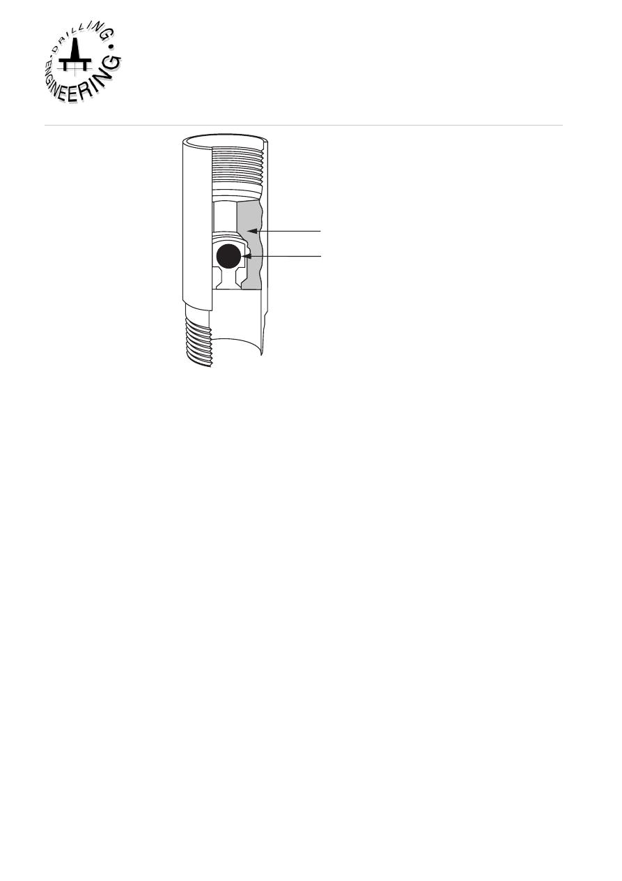
• Guide shoe - A guide (Figure 5) shoe is run on the bottom of the first joint of
casing. It has a rounded nose to guide the casing past any ledges or other irregularities
in the hole .
.
Drillable
material
Float valve
Float shoe
Guide shoe
Figure 5
Guide shoe and float shoe
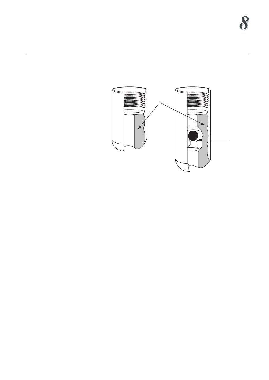
• Float collar - A float collar (Figure 6) is positioned 1 or 2 joints above the guide
shoe. It acts as a seat for the cement plugs used in the pumping and displacement
of the cement slurry. This means that at the end of the cement job there will be
some cement left in the casing between the float collar and the guide shoe which
must be drilled out.
The float collar also contains a non-return valve so that the cement slurry cannot
flow back up the casing. This is necessary because the cement slurry in the annulus
generally has a higher density than the displacing fluid in the casing, therefore a
U-tube effect is created when the cement is in position and the pumps are stopped.
Sometimes the guide shoe also has a non-return valve as an extra precaution. It is
essential that the non-return valves are effective in holding back the cement slurry.
1
Drillable
material
Float valve
Figure 6
Float collar
The use of a non-return valve means that as the casing is being run into the borehole
the fluid in the hole cannot enter the casing from below. This creates a buoyancy
effect which can be reduced by filling up the casing from the surface at regular
intervals while the casing is being run (every 5 - 20 joints). This filling up process
increases the running in time and can be avoided by the use of automatic or
differential fill up devices fitted to the float collar or shoe. These devices allow a
controlled amount of fluid to enter the casing at the bottom of the string. The ports
through which the fluid enters are blocked off before the cement job begins. The
use of a differential fill-up device also reduces the effect of surge pressures on the
formation .
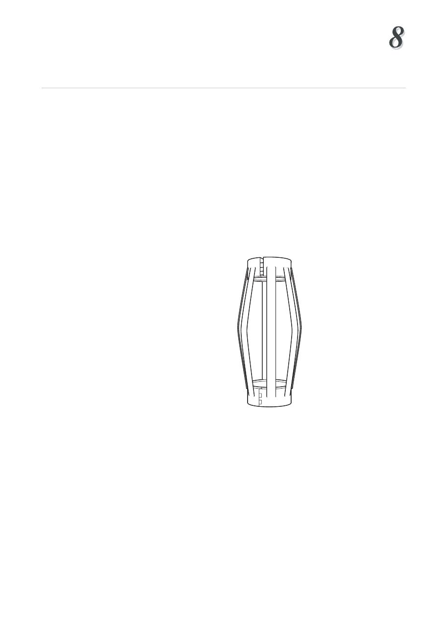
• Centralisers - these are hinged metal ribs which are installed on the casing
string as it is run (Figure 7). Their function is to keep the casing away from the
borehole so that there is some annular clearance around the entire circumference
of the casing
The proper use of centralisers will help to:
• Improve displacement efficiency (i.e. place cement all the way around the
casing)
• Prevent differential sticking
• Keep casing out of keyseats
Cementing
1
Institute of Petroleum Engineering, Heriot-Watt University
Centralisers are particularly required in deviated wells where the casing tends to lie
on the low side of the hole. On the high side there will be little resistance to flow,
and so cement placement will tend to flow up the high side annular space. Mud
channels will tend to form on the low side of the hole, preventing a good cement
job. Each centraliser is hinged so that it can be easily clamped onto the outside of
the casing and secured by a retaining pin. The centraliser is prevented from moving
up and down the casing by positioning the centraliser across a casing coupling or a
collar known as a stop collar. The spacing of centralisers will vary depending on
the requirements of each cement job. In critical zones, and in highly deviated parts
of the well, they are closely spaced, while on other parts of the casing string they
may not be necessary at all. A typical programme might be:
1 centraliser immediately above the shoe
1 every joint on the bottom 3 joints
1 every joint through the production zone
1 every 3 joints elsewhere
Figure 7
Casing Centraliser
• Wipers/scratchers - these are devices run on the outside of the casing to remove
mud cake and break up gelled mud. They are sometimes used through the
production zone.
1
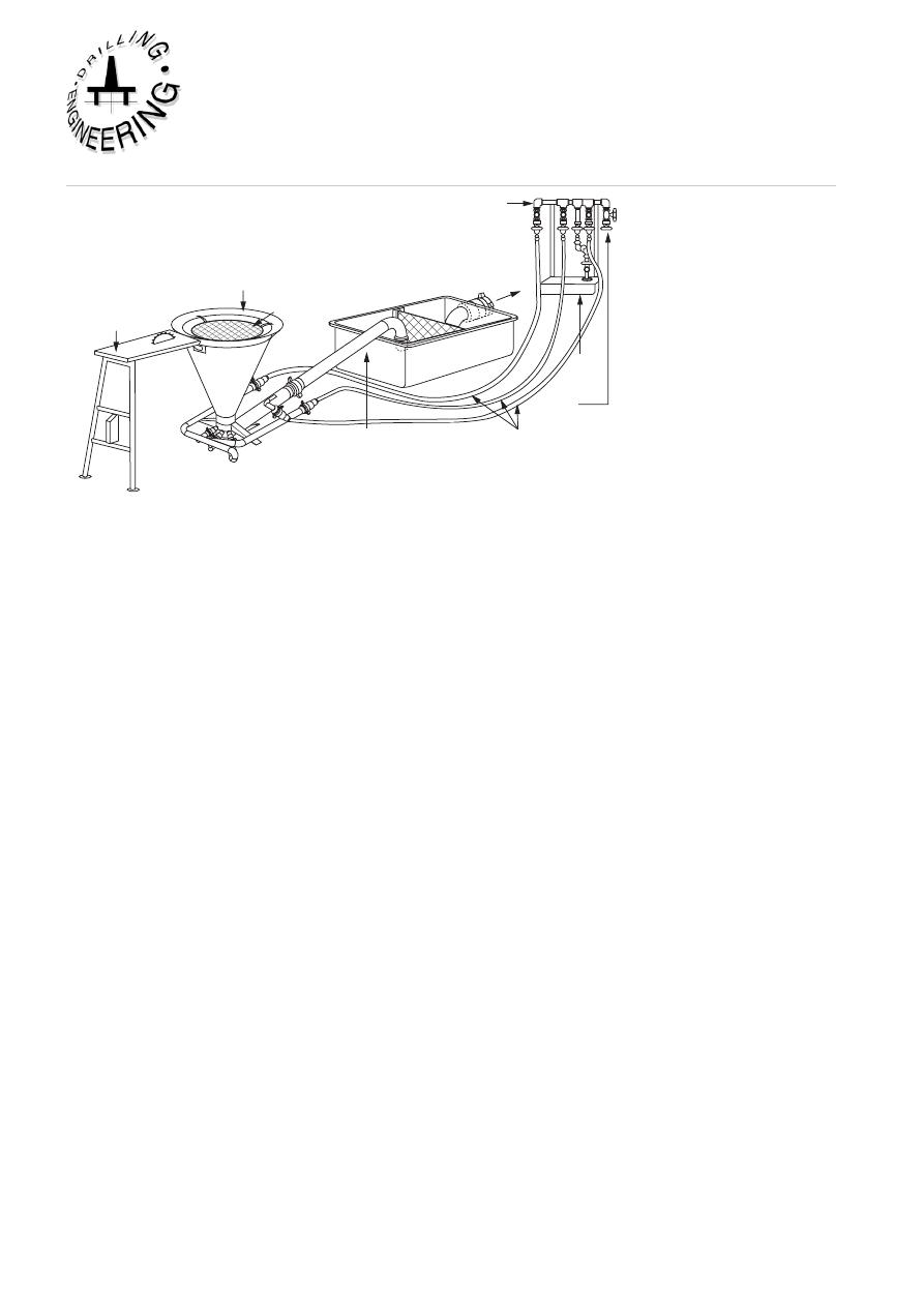
Cutting table
Hopper
Screen
Slurry tub
Mixing manifold
To triplex pump
slurry suction
Fluid end
HP hoses
To centrifugal
pump
Discharge gooseneck
Jet mixer
Figure 8
Cement unit showing jet mixer
4.2 Surface cementing equipment
Mixing and pumping facilities:
On most rigs cement powder and additives are handled in bulk, which makes
blending and mixing much easier. For large volume cement jobs several bulk
storage bins may be required on the rig. On offshore rigs the cement is transferred
pneumatically from supply boats to the storage bins.
For any cement job there must be sufficient water available to mix the slurry at the
desired water/cement ratio when required. The mix water must also be free of all
contaminants.
The water is added to the cement in a jet mixer (Figure 8). The mixer consists of
a funnel shaped hopper, a mixing bowl, a water supply line and an outlet for the
slurry. As the mixwater is pumped across the lower end of the hopper a venturi
effect is created and cement powder is drawn down into the flow of mixwater and
a slurry is created. The slurry flows into a slurry tub where its density is measured.
The density of the slurry should be regularly checked during the cement job since
this is the primary means by which the quality of the slurry is determined. If the
density of the slurry is correct then the correct amount of mixwater has been mixed
with the cement powder. Samples can be taken directly from the mixer and weighed
in a standard mud balance or automatic devices (densometers) can also be used.
Various types of cement pumping units are available. For land based jobs they
can be mounted on a truck, while skid mounted units are used offshore. The unit
normally has twin pumps (triplex, positive displacement) which may be diesel
powered or driven by electric motors. These units can operate at high pressures
(up to 20,000 psi) but are generally limited to low pumping rates. Most units are
capable of mixing and displacing 50 - 70 cubic feet of slurry per minute. In order
to minimise contamination by the mud in the annulus a preflush or spacer fluid is
pumped ahead of the cement slurry. The actual composition of the spacer depends
Cementing
1
Institute of Petroleum Engineering, Heriot-Watt University
on the type of mud being used. For water based muds the spacer fluid is often just
water, but specially designed fluids are available. The volume of spacer is based on
the need to provide sufficient separation of mud and cement in the annulus (20 - 50
bbls of spacer is common).
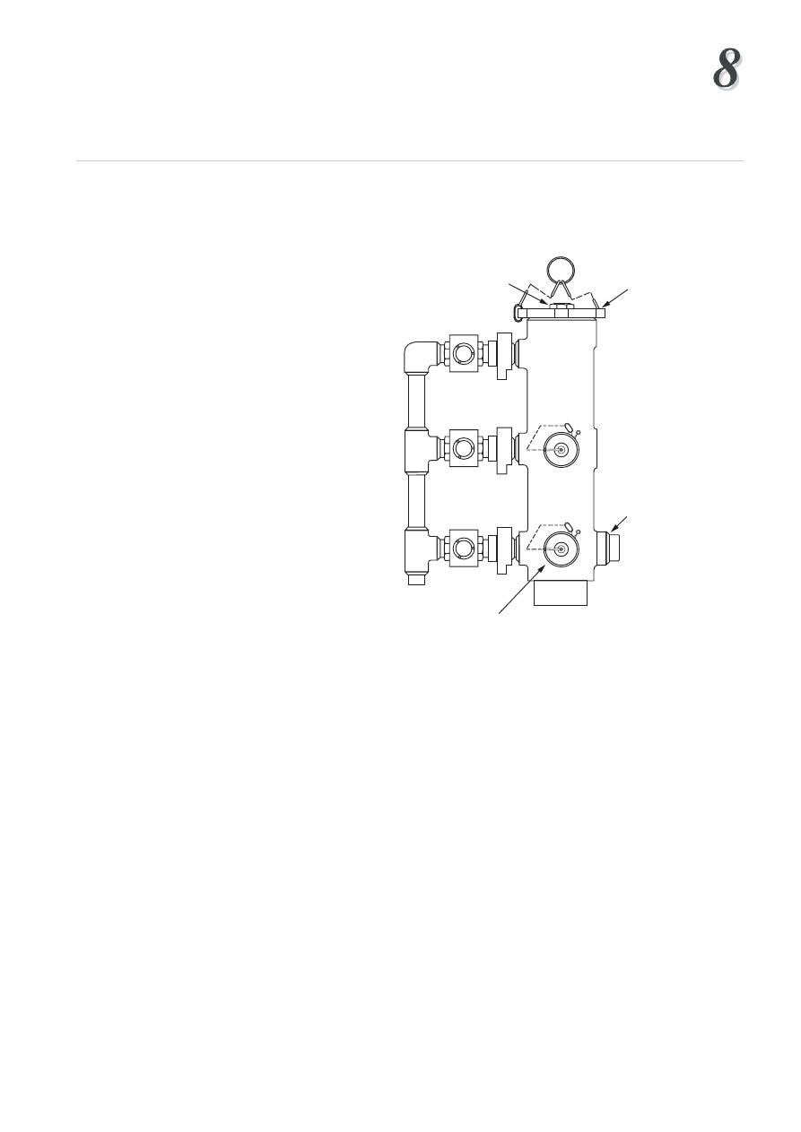
Hex plug
Cap
Body
Bull plug
Bail assy.
w/lock bolt
Manifold
assembly:
2" pipe
fittings
Figure 9
Cement Head
Cementing heads:
The cement head provides the connection between the discharge line from the
cement unit and the top of the casing (Figure 9). This piece of equipment is
designed to hold the cement plugs used in the conventional primary cement job.
The cement head makes it possible to release the bottom plug, mix and pump down
the cement slurry, release the top plug and displace the cement without making or
breaking the connection to the top of the casing. For ease of operation the cement
head should be installed as close to rig floor level as possible. The cement jobs will
be unsuccessful if the cement plugs are installed in the correct sequence or are not
released from the cementing head.
Mud is normally used to displace the cement slurry. The cement pumps or the rig
pumps may be used for the displacement. It is recommended that the cement slurry
is displaced at as high a rate as possible. High rate displacement will aid efficient
mud displacement. It is highly unlikely that it will be possible to achieve turbulence
in the cement slurry since it is so viscous and has such a high density. However, it
may be possible to generate turbulence in the spacer and this will result in a more
efficient displacement of the mud.
0
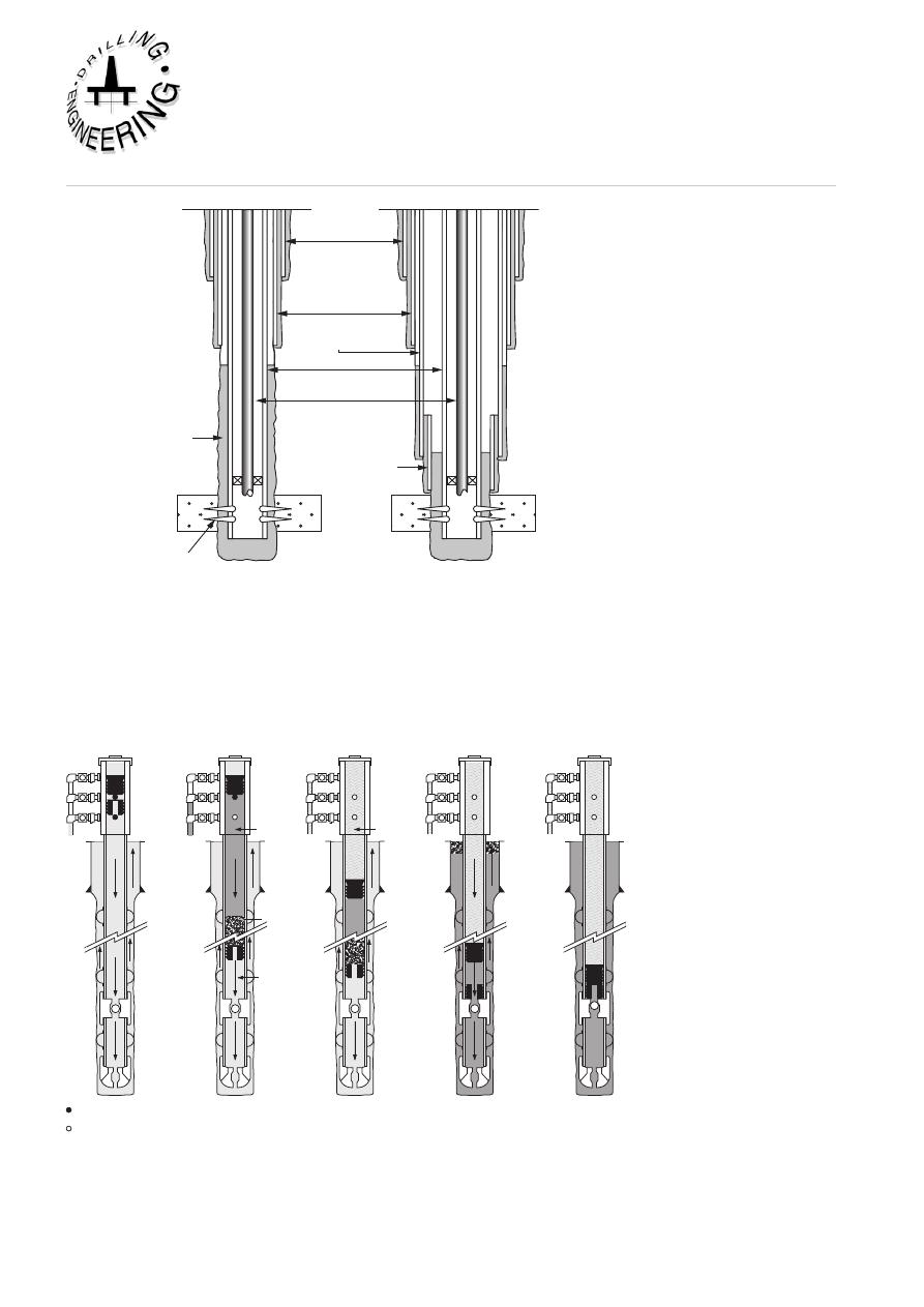
4.3 Single Stage Cementing Operation
The single stage primary cementing operation is the most common type of cementing
operation that is conducted when drilling a well. The procedure for performing a
single stage cementing operation (Figure 10) will be discussed first and then the
procedure for conducting a multiple stage and stinger cementing operations
will be discussed.
Circulating
mud
Pumping spacer
and slurry
Displacing
Displacing
End of job
Top
cementing
plug
Bottom
cementing
plug
Centralizers
Float
collar
Shoe
Spacer
Slurry
Displacing
Fluid
Original
mud
Plug release pin in
Plug release pin out
Figure 10
Single Stage Cementing Operation
In the case of the single stage operation, the casing with all of the required cementing
accessories such as the float collar, centralisers etc. is run in the hole until the shoe is
just a few feet off the bottom of the hole and the casing head is connected to the top
of the casing. It is essential that the cement plugs are correctly placed in the cement
head. The casing is then circulated clean before the cementing operation begins (at
least one casing volume should be circulated). The first cement plug (wiper plug)
shown in Figure 11, is pumped down ahead of the cement to wipe the inside of the
casing clean. The spacer is then pumped into the casing. The spacer is followed by
the cement slurry and this is followed by the second plug (shut-off plug) shown
in Figure 12. When the wiper plug reaches the float collar its rubber diaphragm is
ruptured, allowing the cement slurry to flow through the plug, around the shoe, and
up into the annulus. At this stage the spacer is providing a barrier to mixing of the
cement and mud. When the solid, shut-off plug reaches the float collar it lands on
the wiper plug and stops the displacement process. The pumping rate should be
slowed down as the shut-off plug approaches the float collar and the shut-off plug
should be gently bumped into the bottom, wiper plug. The casing is often pressure
tested at this point in the operation. The pressure is then bled off slowly to ensure
that the float valves, in the float collar and/or casing shoe, are holding.
Cementing
1
Institute of Petroleum Engineering, Heriot-Watt University
The displacement of the top plug is closely monitored. The volume of displacing
fluid necessary to bump the plug should be calculated before the job begins. When
the pre-determined volume has almost been completely pumped, the pumps should
be slowed down to avoid excessive pressure when the plug is bumped. If the top
plug does not bump at the calculated volume (allowing for compression of the mud)
this may be because the top, shut-off plug has not been released. If this is the case,
no more fluid should be pumped, since this would displace the cement around the
casing shoe and up the annulus. Throughout the cement job the mud returns from
the annulus should be monitored to ensure that the formation has not been broken
down. If formation breakdown does occur then mud returns would slow down or
stop during the displacement operation.
The single stage procedure can be summarised as follows:
1. Circulate the casing and annulus clean with mud (one casing volume pumped)
2. Release wiper plug
3. Pump spacer
4. Pump cement
5. Release shut-off plug
6. Displace with displacing fluid (generally mud) until the shut-off plug lands on
the float collar
7. Pressure test the casing
Rupture Disk
Moulded
Elastomer
Aluminium
Core
Figure 11
Bottom Plug (wiper plug)
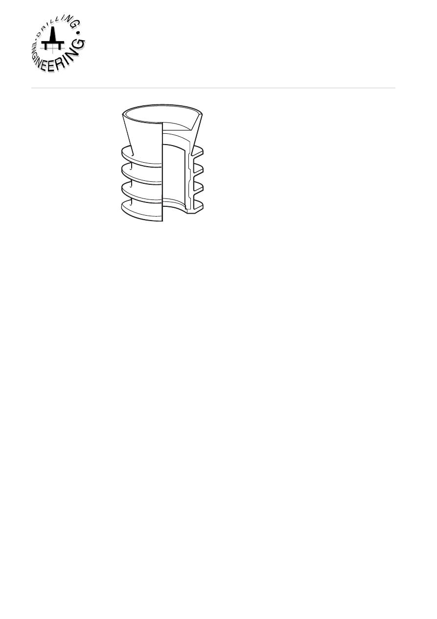
Figure 12
Top Plug (shut off plug)
4.4 Multi - Stage Cementing Operation
When a long intermediate string of casing is to be cemented it is sometimes necessary
to split the cement sheath in the annulus into two, with one sheath extending from the
casing shoe to some point above potentially troublesome formations at the bottom
of the hole, and the second sheath covering shallower troublesome formations. The
placement of these cement sheaths is known as a multi-stage cementing operation
(Figure 13). The reasons for using a multi-stage operation are to reduce:
• Long pumping times
• High pump pressures
• Excessive hydrostatic pressure on weak formations due to the relatively high
density of cement slurries.
Cementing
Institute of Petroleum Engineering, Heriot-Watt University
Figure 13
Multi-Stage Cementing Operation
The procedure for conducting a multi-stage operation is as follows:
First stage
The procedure for the first stage of the operation is similar to that described in
Section 4.3 above, except that a wiper plug is not used and only a liquid spacer is
pumped ahead of the cement slurry. The conventional shut-off plug is replaced by
a plug with flexible blades. This type of shut-off plug is used because
it has to pass through the stage cementing collar which will be discussed below. It
is worth noting that a smaller volume of cement slurry is used, since only the lower
part of the annulus is to be cemented. The height of this cemented part of the
annulus will depend on the fracture gradient of the formations which are exposed in
the annulus (a height of 3000' - 4000' above the shoe is common).
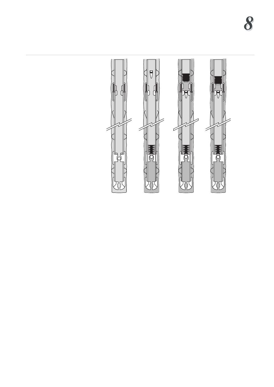
Second stage
The second stage of the operation involves the use of a special tool known as a
stage collar (Figure 14), which is made up into the casing string at a pre-determined
position. The position often corresponds to the depth of the previous casing shoe.
The ports in the stage collar are initially sealed off by the inner sleeve. This sleeve
is held in place by retaining pins. After the first stage is complete a special dart is
released form surface which lands in the inner sleeve of the stage collar. When a
pressure of 1000 - 1500 psi is applied to the casing above the dart, and therefore
to the dart, the retaining pins on the inner sleeve are sheared and the sleeve moves
down, uncovering the ports in the outer mandrel. Circulation is established through
the stage collar before the second stage slurry is pumped.
The normal procedure for the second stage of a two stage operation is as follows:
1 Drop opening dart
2 Pressure up to shear pins
3 Circulate though stage collar whilst the first stage cement is setting
4 Pump spacer
5 Pump second stage slurry
6 Release closing plug
7 Displace plug and cement with mud
8 Pressure up on plug to close ports in stage collar and pressure test the casing.
Closing
sleeve
Lock
ring
Shear
pin
Drillable
opening
seat
Opening
sleeve
Ports
Figure 14
Multi-Stage Cementing Collar
To prevent cement falling down the annulus a cement basket or packer may be run
on the casing below the stage collar. If necessary, more than one stage collar can
be run on the casing so that various sections of the annulus can be cemented. One
disadvantage of stage cementing is that the casing cannot be moved after the first
stage cement has set in the lower part of the annulus. This increases the risk of
channelling and a poor cement bond.

Cementing
Institute of Petroleum Engineering, Heriot-Watt University
4.5 Inner string cementing
For large diameter casing, such as conductors and surface casing, conventional
cementing techniques result in:
• The potential for cement contamination during pumping and displacement
• The use of large cement plugs which can get stuck in the casing
• Large displacement volumes
• Long pumping times
• Large volume of cement left inside the casing between float collar and shoe.
An alternative technique, known as a stinger cement job, is to cement the casing
through a tubing or drillpipe string, known as a cement stinger, rather than through
the casing itself.
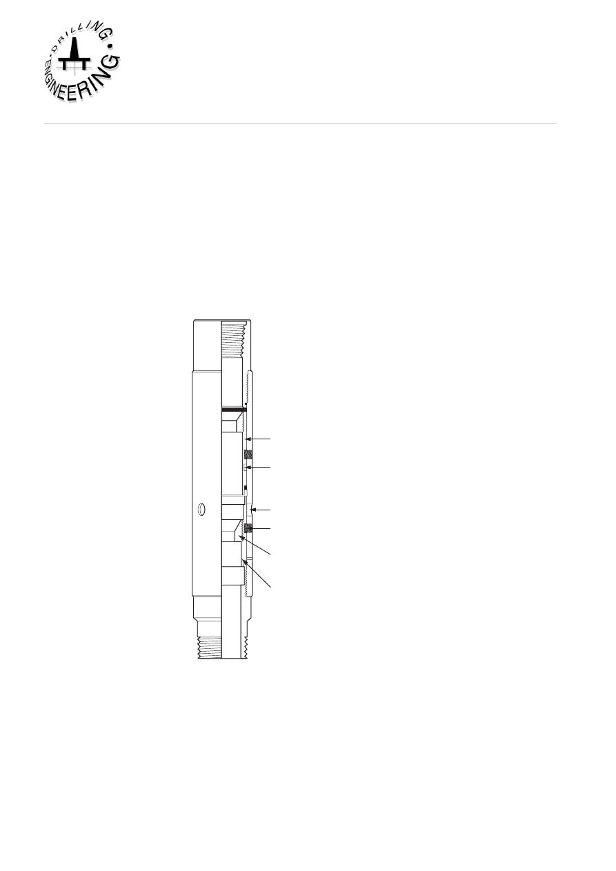
In the case of a stinger cement job the casing is run as before, but with a special
float shoe (Figure 15) rather than the conventional shoe and float collar. A special
sealing adapter, which can seal in the seal bore of the seal float shoe, is attached to
the cement stinger. Once the casing has been run, the cementing string (generally
tubing or drillpipe), with the seal adapter attached, is run and stabbed into the float
shoe. Drilling mud is then circulated around the system to ensure that the stinger
and annulus are clear of any debris. The cement slurry is then pumped with liquid
spacers ahead and behind the cement slurry. No plugs are used in this type of
cementing operation since the diameter of the stinger is generally so small that
contamination of the cement is unlikely if a large enough liquid spacer is used.
The cement slurry is generally under-displaced so that when the seal adapter on
the stinger is pulled from the shoe the excess cement falls down on top of the shoe.
This can be subsequently drilled out when the next hole section is being drilled.
Under-displacement however ensures that the cement slurry is not displaced up
above the casing shoe, leaving spacer and drilling mud across the shoe. After the
cement has been displaced, and the float has been checked for backflow, the cement
stinger can be retrieved. This method is suitable for casing diameters of 13 3/8" and
larger. The main disadvantage of this method is that for long casing strings rig time
is lost in running and retrieving the inner string.
Tool joint
adapter
Sealing
adapter
Sealing
sleeve
Super seal
float shoe
Special
float shoe
Casing
Cement
Drillpipe
or tubing
Figure 15
Stinger Cementing Operation
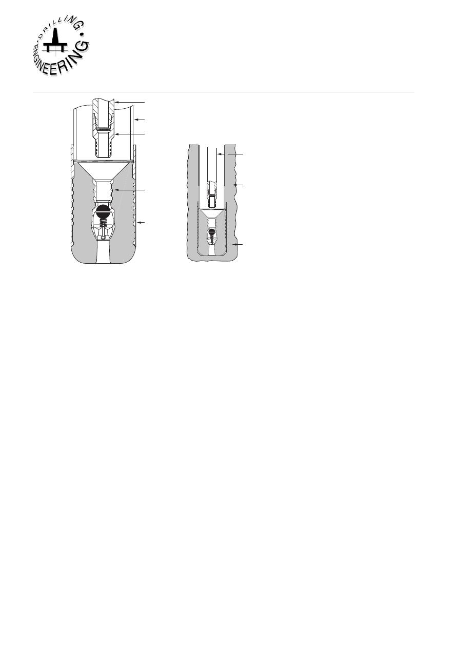
4.6 Liner cementing
Liners are run on drillpipe and therefore the conventional cementing techniques
cannot be used for cementing a liner. Special equipment must be used for cementing
these liners.
As with a full string of casing the liner has a float collar and shoe installed. In
addition there is a landing collar, positioned about two joints above the float collar
(Figure 16). A wiper plug is held on the end of the tailpipe of the running string by
shear pins.
Cementing
Institute of Petroleum Engineering, Heriot-Watt University
Float shoe
Cementing
head
Setting tool
Hanger slips
Centralizers
Float collar
Landing collar
Wiper plug
Slick joint
Packoff
Tie- back
sleeve
Cementing
manifold
Figure 16
Liner Cementing Equipment
The liner is run on drillpipe and the hanger is set at the correct point inside the
previous casing string. Mud is circulated to ensure that the liner and the annulus is
free from debris, and to condition the mud. Before the cementing operation begins
the liner setting tool is backed off to ensure that it can be recovered at the end of the
cement job. The cementing procedure is as follows:
1 Pump spacer ahead of cement slurry
2 Pump slurry
3 Release pump down plug
4 Displace cement down the running string and out of the liner into the annulus
5 Continue pumping until the pump down plug lands on the wiper plug.
6 Apply pressure to the pump down plug and shear out the pins on the wiper
plug. This releases the wiper plug
7 Both plugs move down the liner until they latch onto landing collar
8 Bump the plugs with 1000 psi pressure
9 Bleed off pressure and check for back flow
Since there is no bottom plug in front of the slurry the wiper plug cleans off debris
and mud from the inside of the liner. This material will contaminate the cement
immediately ahead of the wiper plug. The spacing between the landing collar and
the shoe should be adequate to accommodate this contaminated cement, and thus
prevent it from reaching the annulus where it would create a poor cement job
around the shoe.

To promote a good cement job, cement in excess of that required to fill the annulus
between the liner and the borehole is used. This excess cement will pass up around
the liner top and settle on top of the liner running assembly. Once the cement is in
place the liner setting tool is quickly picked up out of the liner. With the tail pipe
above the liner top the excess cement can be reverse circulated out. The setting tool
can then be retrieved.
In practice it is very difficult to obtain a good cement job on a liner. The main
reasons for this are:
(a) Minimal annular clearances
A 7" OD liner run in an 8 1/2" hole gives a clearance of only 3/4" (assuming the
liner is perfectly centred). This small clearance means that:
• It is difficult to run the liner (surge pressure)
• High pressure drops occur during circulation (lost circulation problems)
• It is difficult to centralise the liner
• Cement placement is poor (channeling)
(b) Mud contamination
When the cement comes in contact with mud or mud cake it may develop high
viscosity. The increased pump pressure required to move this contaminated cement
up the annulus may cause formation breakdown. Fluid loss additives must be used
to prevent dehydration of the cement which may cause bridging in the annulus.
(c) Lack of pipe movement
Due to risk of sticking the setting tool, most operators want to be free of the liner
before cementing begins. By disconnecting the setting tool the liner cannot be moved
during the cement job. This lack of movement reduces the efficiency of cement
placement. Due to these problems it is often necessary to carry out a remedial
squeeze job at the top of the liner (Figure17). It is becoming more common these
days to remain latched on top of the liner and rotate the liner whilst the cement is
being displaced into position. A special piece of liner running equipment, known
as a rotating liner assembly, is used for this purpose.
Cementing
Institute of Petroleum Engineering, Heriot-Watt University
Tubing
Retainer or
retrievable packer
Top of liner
Cement
Figure 17
Remedial squeeze job on a liner
4.7 Recommendations for a good cement job
The main cause for poor isolation after a cement job is the presence of mud channels
in the cement sheath in the annulus. These channels of gelled mud exist because
the mud in the annulus has not been displaced by the cement slurry. This can occur
for many reasons. The main reason for this is poor centralisation of the casing in
the borehole, during the cementing operation. When mud is being displaced from
the annulus the cement will follow the least path of resistance. If the pipe is not
properly centralised the highest resistance to flow occurs where the clearance is
least. This is where mud channels are most likely to occur (Figure 18).
In addition, field tests have shown that for a good cement bond to develop the
formation should be in contact with the cement slurry for a certain time period
while the cement is being displaced. The recommended contact time (pump past
time) is about 10 minutes for most cement jobs. To improve mud displacement and
obtain a good cement bond the following practices are recommended:
• Use centralisers, especially at critical points in the casing string
• Move the casing during the cement job. In general, rotation is preferred to
reciprocation, since the latter may cause surging against the formation. A specially
designed swivel may be installed between the cementing head and the casing to
allow rotation. (Centralisers remain static and allow the casing to rotate within
them.)
• Before doing the cement job, condition the mud (low PV, low YP) to ensure
good flow properties, so that it can be easily displaced.
0
• Displace the spacer is in turbulent flow. This may not be practicable in large
diameter casing where the high pump rates and pressures may cause erosion or
formation breakdown.
• Use spacers to prevent mud contamination in the annulus.
Cement
100% Standoff
Mud
75% Standoff
50% Standoff
Figure 18
Effect of centralisation on channeling
5. SQuEEZE CEMENTiNg
Squeeze cementing is the process by which hydraulic pressure is used to force
cement slurry through holes in the casing and into the annulus and/or the formation.
Squeeze cement jobs are often used to carry out remedial operations during a
workover on the well (Figure 3). The main applications of squeeze cementing are:
• To seal off gas or water producing zones, and thus maximise oil production
from the completion interval
• To repair casing failures by squeezing cement through leaking joints or
corrosion hole
• To seal off lost circulation zones
• To carry out remedial work on a poor primary cement job (e.g. to fill up the
annulus)
• To prevent vertical reservoir fluid migration into producing zones (block
squeeze)
• To prevent fluids escaping from abandoned zones.

Cementing
1
Institute of Petroleum Engineering, Heriot-Watt University
During squeeze cementing the pores in the rock rarely allow whole cement to enter
the formation since a permeability of about 500 darcies would be required for this
to happen. There are two processes by which cement can be squeezed:
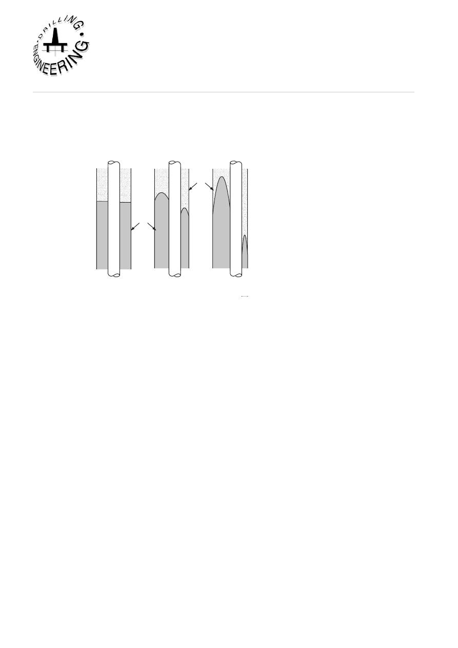
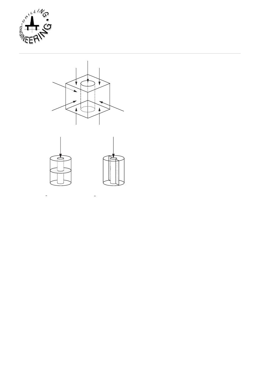
• High pressure squeeze - This technique requires that the formation be fractured.
which then allows the cement slurry to be pumped into the fractured zone.
• Low pressure squeeze - During this technique the fracture gradient of the formation
is not exceeded. Cement slurry is placed against the formation, and when pressure
is applied the fluid content (filtrate) of the cement is squeezed into the rock, while
the solid cement material (filter cake) builds up on the face of the formation.
5.1 High Pressure Squeeze
In a high pressure squeeze the formation is initially fractured (broken down) by
a solids free breakdown fluid. A solids free fluid is used because a solids laiden
fluid such as drilling mud will build up a filter cake and prevent injection into the
formation. Solids free fluids such as water or brine are recommended. The direction
of the fracture depends on the rock stresses present in the formation. The fracture
will occur along a plane perpendicular to the direction of the least compressive
stress (Figure 19). In general, the vertical stress, due to the overburden, will be
greater than the horizontal stresses. A vertical fracture is therefore more likely.
In practice the fracture direction is difficult to predict since it may follow natural
fractures in the formation. Since squeeze cementing is often used to isolate various
horizontal zones a vertical fracture is of little use (vertical fluid movement is not
prevented).
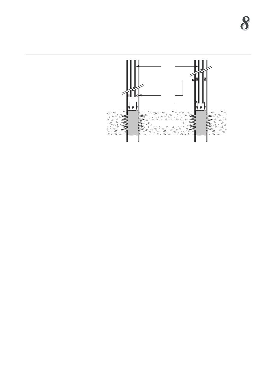
Effect of well depth and vertical-horizontal formation stresses on type of hydraulic fracture
induced by injected fluid. Horizontal fracture pressure is less than overburden pressure,
this is usually the case at depths greater than 3,000 feet.
Wellbore fracture pressure PF
PF
PF
Vertical stress
σv
Horizont
al stress
σh1
Induced horizontal fracture
Induced vertical fracture
PF>σv ; σv<σH1 or σH2
PF>σH1or σH2 ; σH1or σH2< σv
Figure 19
Horizontal and vertical fracturing
After the formation is broken down a slurry of cement is spotted adjacent to the
formation, and then pumped into the zone at a slow rate. The injection pressure
should gradually build up as the cement fills up the fractured zone. After the cement
has been squeezed the pressure is released to check for back flow. The disadvantages
of this technique are:
• No control over the orientation of the fracture
• Large volumes of cement may be necessary to seal off the fracture
• Mud filled perforations may not be opened up by fracturing, so the cement
may not seal them off effectively.
5.2 Low Pressure Squeeze
It is generally accepted that a low pressure squeeze is a more efficient method of
sealing off unwanted perforated zones. In a low pressure squeeze the formation is
not fractured. Instead a cement slurry is gently squeezed against the formation. A
cement slurry consists of finely divided solids dispersed in a liquid. The solids are
too large to be displaced into the formation. As pressure is applied, the liquid phase

Cementing
Institute of Petroleum Engineering, Heriot-Watt University
is forced into the pores, leaving a deposit of solid material or filter cake behind. As
the filter cake of dehydrated cement begins to build up, the impermeable barrier
prevents further filtrate invasion. The filtrate must then be diverted to other parts of
the perforated interval. This technique therefore creates an impermeable seal across
the perforated zone. Fluid loss additives are important to perform this technique
successfully. Neat cement has a high fluid loss, resulting in rapid dehydration which
causes bridging before the other perforations are sealed off. Conversely a very low
fluid loss means a slow filter cake build up and long cement placement time. Key
factors which affect the build up of cement filter cake are:
• Fluid loss (generally 50 - 200 cc)
• Water to solids ratio (0.4 by weight)
• Formation characteristics (permeability, pore pressure)
• Squeeze pressure
Only a small volume of cement is required for a low pressure squeeze. Perforations
must be free from mud or other plugging material. If the well has been producing
for some time these perforations have to be washed out, sometimes with an acid
solution. The general procedure for a low pressure squeeze job is:
1 Water is pumped into the zone to establish whether the formation can be squeezed
(injectivity test). If water cannot be injected the squeeze job cannot be done without
fracturing the formation
2 Spot the cement slurry at the required depth
3 Apply moderate squeeze pressure
4 Stop pumping and check for bleed off
5 Continue pumping until bleed off ceases for about 30 mins
6 Stop displacement of cement and hold pressure
7 Reverse circulate out excess cement from casing
A properly designed slurry will leave only a small cement node inside the casing
after removing the excess cement. Throughout the procedure squeeze pressure
is kept below the fracture gradient. A running squeeze is where the cement is
pumped slowly and continuously until the final squeeze pressure is obtained. This
is often used for repairing a primary cement job. A hesitation squeeze is where
pumping is stopped at regular intervals to allow time for the slurry to dehydrate and
form a filter cake. Small volumes of cement (1/4 - 1/2 bbl) are pumped each time
separated by a delay of 10 - 15 mins. This technique is dangerous if the cement is
still in contact with the drillpipe or packer.
5.3 Equipment Used for Squeeze Cementing
The high pressure and low pressure squeeze operations can be conducted with or
without packers.
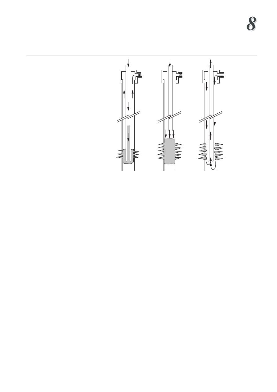
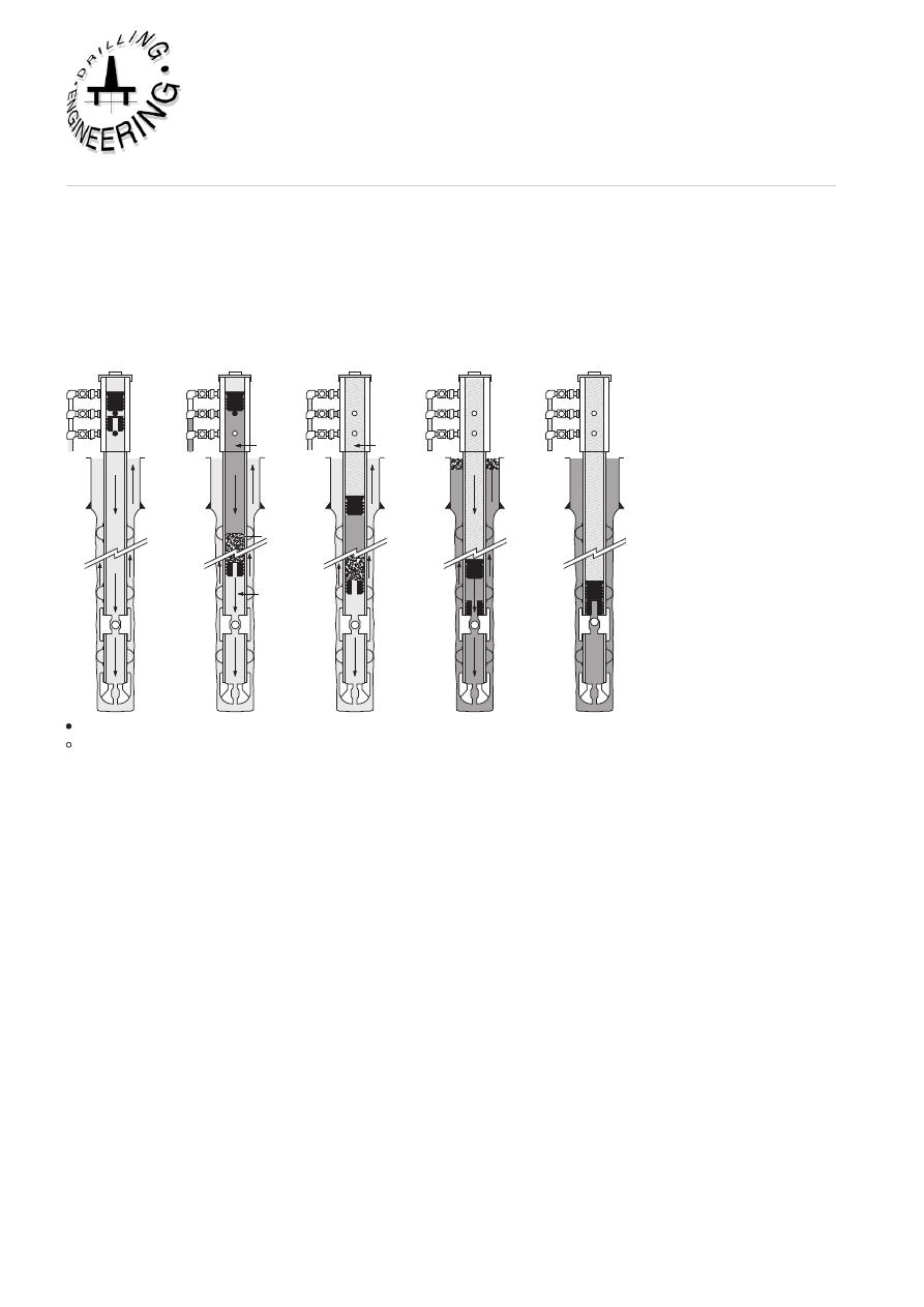
(a) Bradenhead squeeze
This technique involves pumping cement through drill pipe without the use of a
packer (Figure 20). The cement is spotted at the required depth. The BOPs and the
annulus are closed in and displacing fluid is pumped down, forcing the cement into
the perforations, since it cannot move up the annulus. This is the simplest method
of placing and squeezing cement, but has certain disadvantages:
• It is difficult to place the cement accurately against the target zone
• It cannot be used for squeezing off one set of perforations if other
perforations are to remain open
• Casing is pressured up, and so squeeze pressure is limited by burst resistance
A Bradenhead squeeze is only generally used for a low-pressure squeeze job.
Spot cement Apply squeeze Reverse circulate
pressure
Schematic of Bradenhead squeeze technique normally used on low pressure formations.
Cement is circulated into place down drill pipe (left), then the wellhead, or BOP, is closed
(centre) and squeeze pressure is applied. Reverse circulating through perforations (right)
removes excess cement, or the plug can be drilled out.
Figure 20
Bradenhead technique
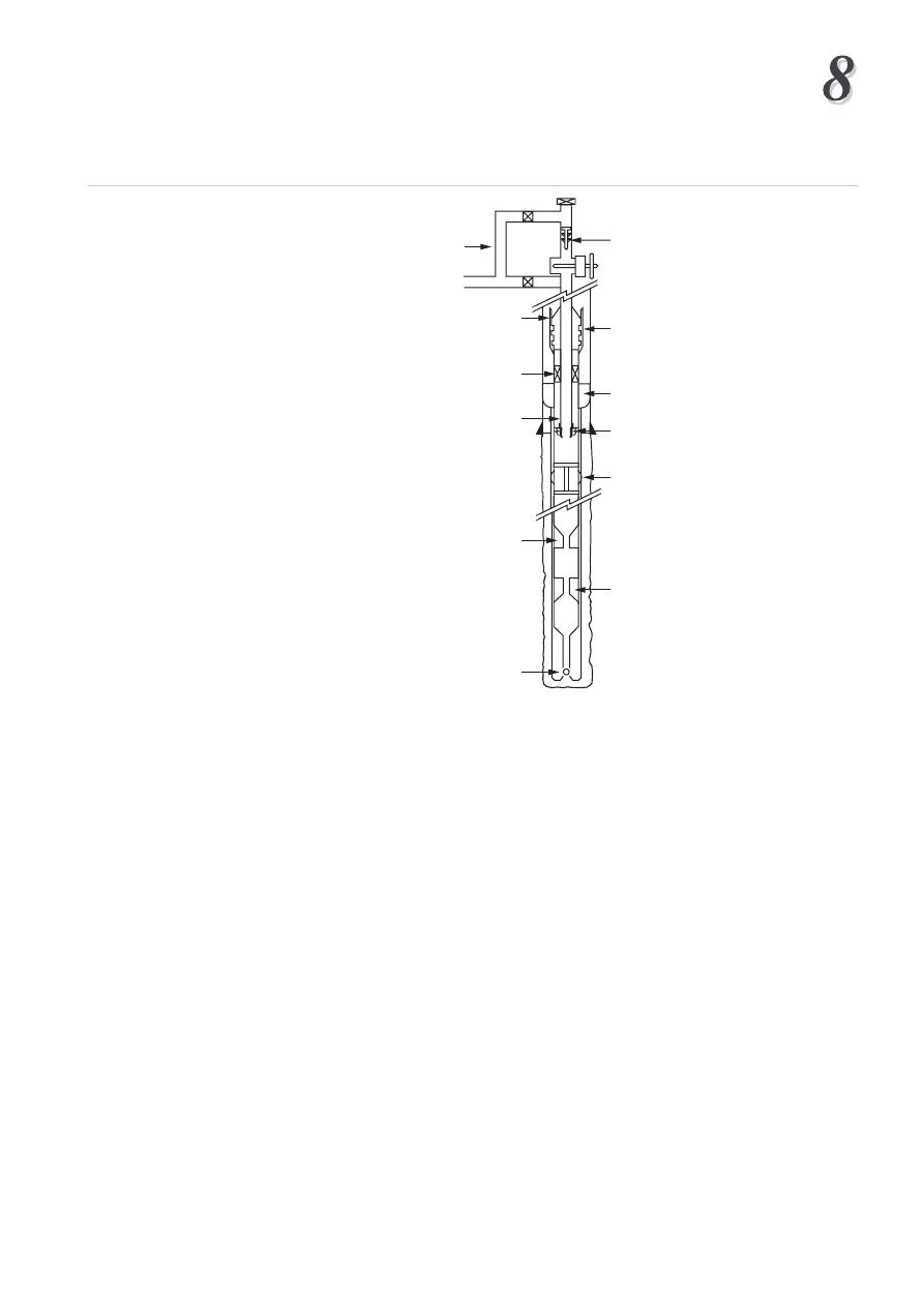
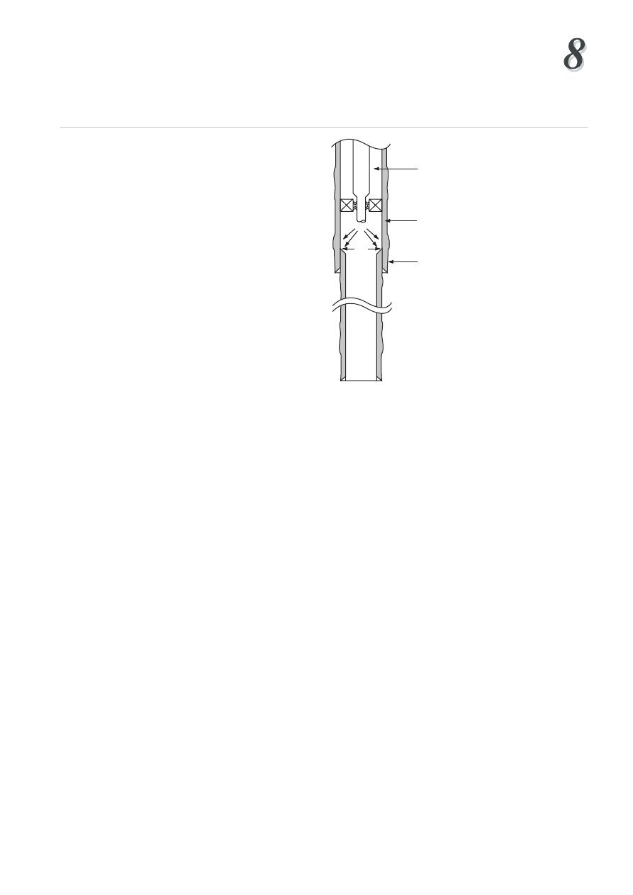
(b) Squeeze using a packer
The use of a packer makes it possible to place the cement more accurately, and apply
higher squeeze pressures. The packer seals off the annulus, but allows communication
between drill pipe and the wellbore beneath the packer. (Figure 21)
Cementing
Institute of Petroleum Engineering, Heriot-Watt University
Tubing
Tailpipe
Perforated Zone
Packer
Figure 21
Squeeze cementing using a packer with or without a tailpipe
Two types of packer may be used in this type of operation:
(i) Drillable packer (cement retainer)
This type of packer contains a back pressure valve which will prevent the cement
flowing back after the squeeze. These are mainly used for remedial work on primary
cement jobs, or to close off water producing zones. The packer is run on drill pipe
or wireline and set just above or between sets of perforations. When the cement
has been squeezed successfully the drill pipe can be removed, closing the back
pressure valve. The advantages of these packers are:
• Good depth control
• Back pressure valve prevents cement back flowing
• Drill pipe recovered without disturbing cement
The major disadvantage is that they can only be used once then drilled out.
(ii) Retrievable packer (cement retainer)
These can be set and released many times on one trip. This makes them suitable for
repairing a series of casing leaks or selectively squeezing off sets of perforations.
By-pass ports in the packer allow annular communication, but these ports are closed
during the squeeze job. When the packer is released there may be some backflow,
and the cement filter cake may be disturbed. If this happens the packer should be
re-set and the squeeze pressure applied until the cement sets.
The basic procedure for squeezing with a retrieveable packer is:
1. run the packer on drillpipe and set it at required depth with by-pass open
2. pump the cement slurry (keep back pressure on annulus to prevent cement falling
The packer setting depth should be considered carefully. If positioned too high
above the perforations the slurry will be contaminated by the wellbore fluids and
large volumes of fluid from below the packer will be pumped into the formation
ahead of the cement. If the packer is set too low it may become stuck in the cement.
Generally the packer is set 30 - 50 ft above the perforations.
Sometimes a tail pipe is used below the packer to ensure that only cement is squeezed
into the perforations, and there is less chance of getting stuck (Figure 21). Bridge
plugs
are often set in the wellbore, to isolate zones which are not to be treated.
They seal off the entire wellbore, and hold pressure from above and below. Bridge
plugs can either be drillable or retrievable.
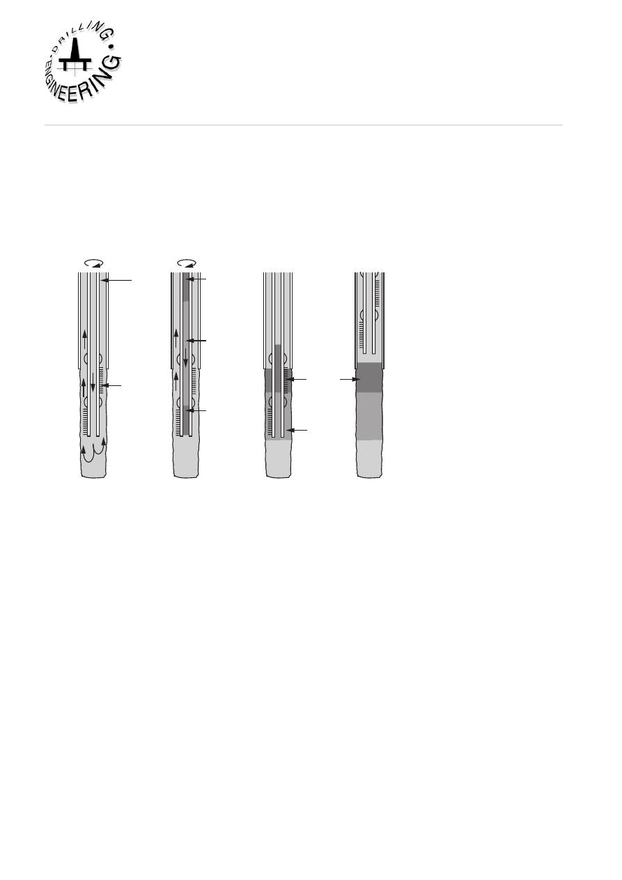
Condition mud
rotation pipe
Displace cement
and fluids
Spot balanced
plug
Pull pipe
slowly
Drill
pipe
Scratch
centralizer
Spacer
Spacer
and
preflush
Cement
Cement
plug
Preflush
Figure 22
Balanced Plug Cementation
5.4 Testing the Squeeze Job
After the cement has hardened it must be pressure tested. The tests should include
both positive and negative differential pressure. The following should be considered
when making a test:
• A positive pressure test can be performed by closing the BOPs and pressuring
up on the casing. (Do not exceed formation fracture gradient.)
• A negative pressure test (or inflow test) can be performed by reducing the
hydrostatic pressure inside the casing. This can be done using a DST tool or
displacing with the well to diesel. This test is more meaningful since mud filled
perforations may hold pressure from the casing, but may become unblocked
when pressure from the formation is applied.
Cementing
Institute of Petroleum Engineering, Heriot-Watt University
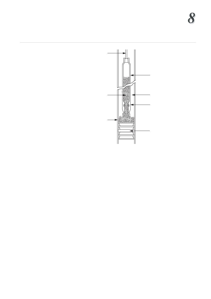
Wire line
Cement
Casing
Dump bailer
Dump release
Mud
Bridge plug
or obstuction
Figure 23
Dump Bailer Plug Cementation
6. CEMENT PLugS
At some stage during the life of a well a cement plug may have to be placed in
the wellbore. A cement plug is designed to fill a length of casing or open hole to
prevent vertical fluid movement. Cement plugs may be used for:
• Abandoning depleted zones
• Seal off lost circulation zones
• Providing a kick off point for directional drilling (eg side- tracking around
fish)
• Isolating a zone for formation testing
• Abandoning an entire well (government regulations usually insist on leaving
a series of cement plugs in the well prior to moving off location).
The major problem when setting cement plugs is avoiding mud contamination
during placement of the cement. Certain precautions should be taken to reduce
contamination.
• Select a section of clean hole which is in gauge, and calculate the volume required
(add on a certain amount of excess). The plug should be long enough to allow
for some contamination (500' plugs are common). The top of the plug should
be 250' above the productive zone
• Condition the mud prior to placing the plug
• Use a preflush fluid ahead of the cement
• Use densified cement slurry (ie less mixwater than normal)

After the cement has hardened the final position of the plug should be checked by
running in and tagging the cement. There are three commonly used techniques for
placing a cement plug:
(a) Balanced plug (Figure 22)
This method is aimed at achieving an equal level of cement in the drillpipe and
annulus. Preflush, cement slurry and spacer fluid are pumped down the drillpipe
and displaced with mud. The displacement continues until the level of cement
inside and outside the drillpipe is the same (hence balanced). If the levels are not
the same then a U-tube effect will take pace. The drillpipe can then be retrieved
leaving the plug in place.
(b) Dump bailer (Figure 23)
A dump bailer is an electrically operated device which is run on wireline. A
permanent bridge plug is set below the required plug back depth. A cement bailer
containing the slurry is then lowered down the well on wireline. When the bailer
reaches the bridge plug the slurry is released and sits on top of the bridge plug. The
advantages of this method are:
• High accuracy of depth control
• Reduced risk of contamination of the cement
the disadvantages are:
• Only a small volume of cement can be dumped at a time - several runs may be
necessary
• It is not suitable for deep wells, unless retarders used.
7. EVaLuaTiON OF CEMENT JOBS
A primary cement job can be considered a failure if the cement does not isolate
undesirable zones. This will occur if:
• The cement does not fill the annulus to the required height between the casing
and the borehole.
• The cement does not provide a good seal between the casing and borehole and
fluids leak through the cement sheath to surface.
• The cement does not provide a good seal at the casing shoe and a poor leak off
test is achieved
When any such failures occur some remedial work must be carried out. A number of
methods can be used to assess the effectiveness of the cement job. These include:
Cementing
Institute of Petroleum Engineering, Heriot-Watt University
90ºF
100ºF 110º
120ºF
700'
800'
900'
1000'
1100'
1200'
1300'
1400'
PROBABLE CEMENT
TOP
Figure 24
Estimating top of cement in annulus by running a temperature log
Radiation Intensity Increases
5800'
5900'
6000'
6100'
Cement top
Base Run
After Run
Figure 25
Estimating top of cement by running radioactivity log
0
detecting Top of Cement (TOC)
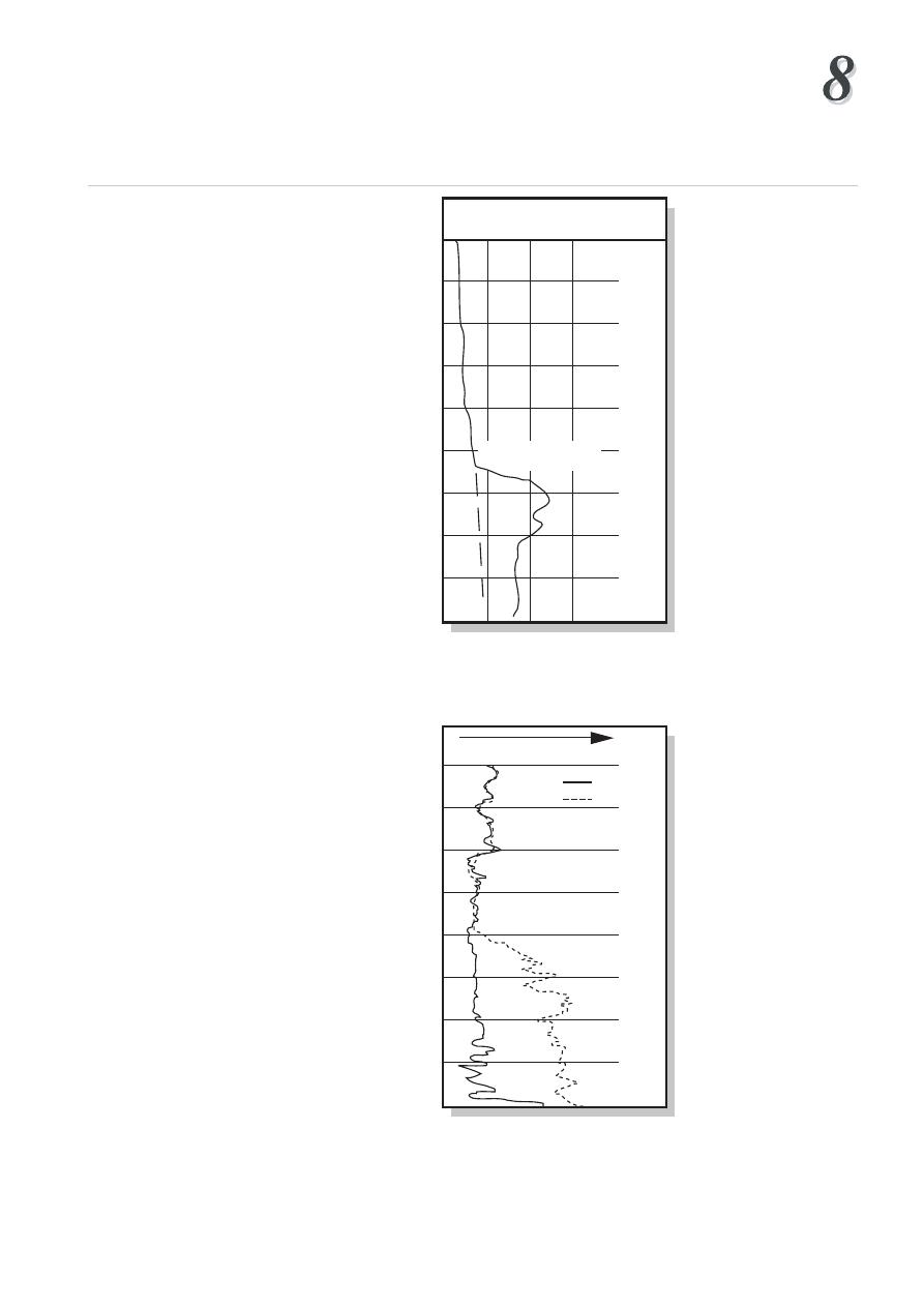
(a) Temperature surveys (Figure 24)
This involves running a thermometer inside the casing just after the cement job.
The thermometer responds to the heat generated by the cement hydration, and so
can be used to detect the top of the cement column in the annulus.
(b) Radioactive surveys (Figure 25)
Radioactive tracers can be added to the cement slurry before it is pumped (Carnolite
is commonly used). A logging tool is then run when the cement job is complete.
This tool detects the top of the cement in the annulus, by identifying where the
radioactivity decreases to the background natural radioactivity of the formation.
detecting Top of Cement (TOC) and the Measuring the Quality of
the Cement Bond
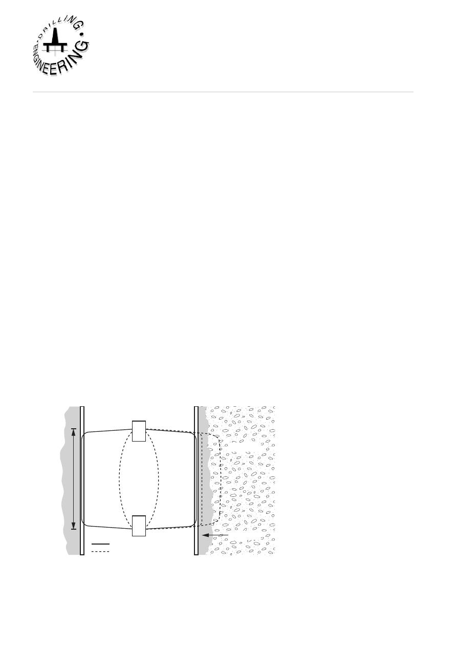
(a) Cement bond logs (CBL)
The cement bond logging tools have become the standard method of evaluating
cement jobs since they not only detect the top of cement, but also indicate how
good the cement bond is. The CBL tool is basically a sonic tool which is run on
wireline. The distance between transmitter and receiver is about 3 ft (Figure 26).
The logging tool must be centralised in the hole to give accurate results. Both the
time taken for the signal to reach the receiver, and the amplitude of the returning
signal, give an indication of the cement bond. Since the speed of sound is greater
in casing than in the formation or mud the first signals which are received at the
receiver are those which travelled through the casing (Figure 27). If the amplitude
(E
1
) is large (strong signal) this indicates that the pipe is free (poor bond). When
cement is firmly bonded to the casing and the formation the signal is attenuated,
and is characteristic of the formation behind the casing.
3 feet
Formation
Cement
Mud
T
R
Shortest path
Longest path
Figure 26
Schematic of CBL tool
Cementing
1
Institute of Petroleum Engineering, Heriot-Watt University
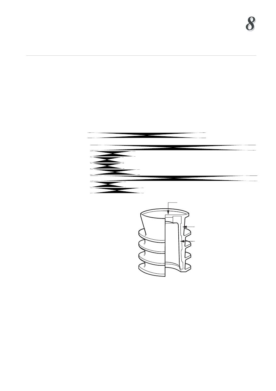
(b) the Variable Density Log (VDL)
The CBL log usually gives an amplitude curve and provides an indication of the
quality of the bond between the casing and cement. A VDL (variable density log),
provides the wavetrain of the received signal (Figure 28), and can indicate the
quality of the cement bond between the casing and cement, and the cement and
the formation. The signals which pass directly through the casing show up as
parallel, straight lines to the left of the VDL plot. A good bond between the casing
and cement and cement and formation is shown by wavy lines to the right of the
VDL plot. The wavy lines correspond to those signals which have passed into and
through the formation before passing back through the cement sheath and casing
to the receiver. If the bonding is poor the signals will not reach the formation and
parallel lines will be recorded all across the VDL plot.
The interpretation of CBL logs is still controversial. There is no standard API scale
to measure the effectiveness of the cement bond. There are many factors which can
lead to false interpretation:
• During the setting process the velocity and amplitude of the signals varies
significantly. It is recommended that the CBL log is not run until 24 - 36 hours
after the cement job to give realistic results.
• Cement composition affects signal transmission
• The thickness of the cement sheath will cause changes in the attenuation of the signal
• The CBL will react to the presence of a microannulus (a small gap between
casing and cement). The microannulus usually heals with time and is not a critical
factor. Some operators recommend running the CBL under pressure to eliminate
the microannulus effect
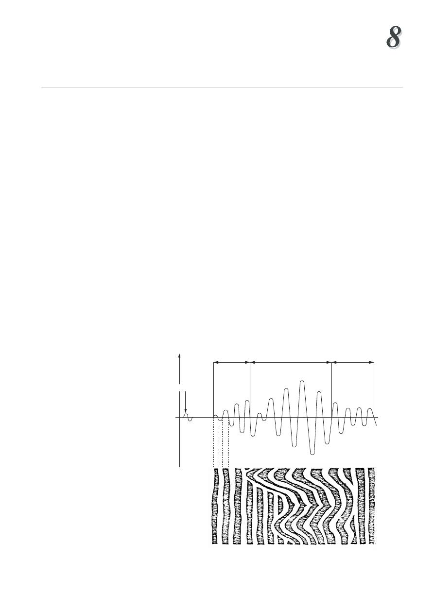
Transmitter
Amplitude
mV
Casing
arrivals
Formation arrivals Mud arrivals
E1
t (µ sec)
Figure 27
Signals picked up by receiver
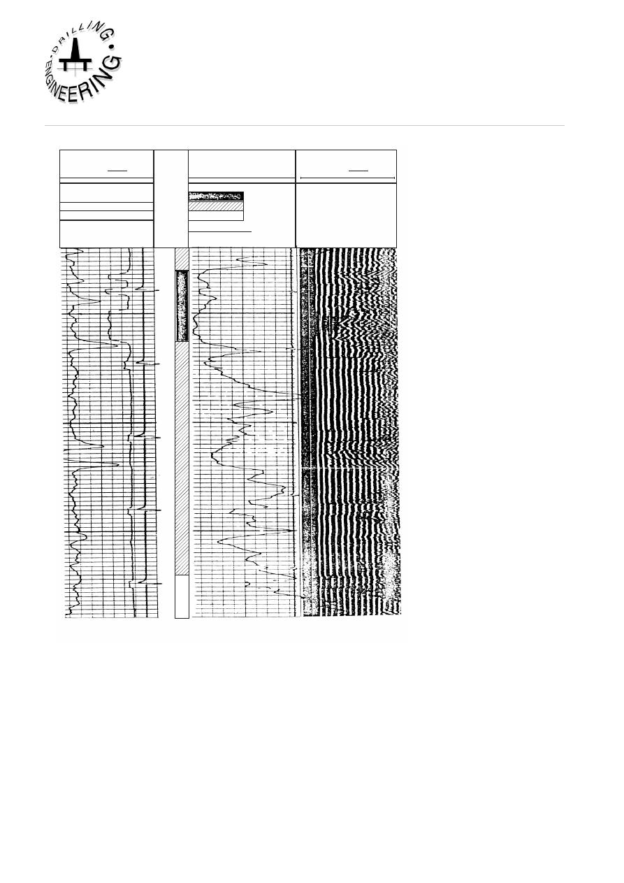
TRANSIT TIME
GAMMA RAY
API UNITS
CASING BOND
BONDING CODE
VARIABLE DENSITY
MICROSECONDS
SPACING
3'
200
100
200
100
MICROSECONDS
SPACING
5'
1200
200
50
0
GOOD BOND
POOR BOND
GOOD
FAIR
POOR
Casing Collars
Corrected Depth
DEPTH
2200
2250
2300
Figure 28
Example of CBL/VDL
CEMENTiNg CaLCuLaTiONS
The following calculations must be undertaken prior to a cementation operation:
• Slurry Requirements
• No. of sacks of Cement
• Volume of Mixwater
• Volume of Additives
• Displacement Volume Duration of Operation
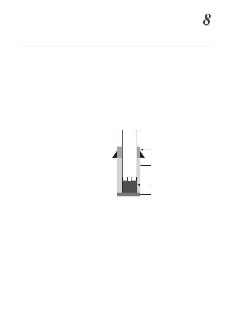
Cementing
Institute of Petroleum Engineering, Heriot-Watt University
These calculations will form the basis of the cementing programme. They should
be performed in this sequence as will be seen below.
1. Cement Slurry Requirements :
Sufficient cement slurry must be mixed and pumped to fill up the following (see Fig
29):
A - the annular space between the casing and the borehole wall,
B - the annular space between the casings (in the case of a two stage
cementation operation)
C - the openhole below the casing (rathole)
D - the shoetrack
The volume of slurry that is required will dictate the amount of dry cement,
mixwater and additives that will be required for the operation.
Casing/Casing Annulus
Casing/Hole Annulus
Shoetrack
Rathole
Figure 29
Single Stage Cementing Operation
In addition to the calculated volumes an excess of slurry will generally be mixed
and pumped to accommodate any errors in the calculated volumes. These errors
may arise due to inaccuracies in the size of the borehole (due to washouts etc.).
It is common to mix an extra 10-20% of the calculated openhole volumes to
accommodate these inaccuracies.
The volumetric capacities (quoted in bbls/linear ft or cuft/limear ft or m3/m) of
the annuli, casings, and open hole are available from service company cementing
tables.. These volumetric capacities can be calculated directly but the cementing
tables are simple to use and include a more accurate assessment of the displacement
of the casing for instance and the capacities based on nominal diameters.
In the case of a two stage operation (Figure 30) the volume of slurry used in the first
stage of the operation is the same as that for a single stage operation. The second
stage slurry volume is the slurry required to fill the annulus between the casing and
hole (or casing/casing if the multi-stage collar is inside the previous shoe) annular
space.
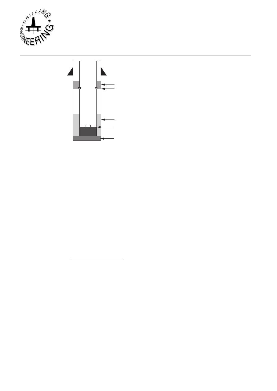
Casing/Hole Annulus
2nd. Stage Annulus
Multi Stage Collar
Shoetrack
Rathole
Figure 30
Two-Stage Cementing Operation
2. Number of Sacks of Cement
Although cement and other dry chemicals are delivered to the rigsite in bulk tanks
the amount of dry cement powder is generally quoted in terms of the number of
sacks (sxs) of cement required. Each sack of cement is equivalent to 1 cu. ft of
cement.
The number of sacks of cement required for the cement operation will depend on
the amount of slurry required for the operation (calculated above) and the amount of
cement slurry that can be produced from a sack of cement. The amount of cement
slurry that can be produced from a sack of cement, known as the yield of the
cement, will depend on the type of cement powder (API classification) and the
amount of mixwater mixed with the cement powder. The latter will also depend
on the type of cement and will vary with pressure and temperature. The number of
sacks of cement required for the operation can be calculated from the following
No. of Sacks =
Total Volume of Slurry
Yield of Cement
3. Mixwater Requirements
The mixwater required to hydrate the cement powder will be prepared and stored
in specially cleaned mud tanks. The amount of mixwater required for the operation
will depend on the type of cement powder used. The volume of mixwater required
for the cement slurry can be calculated from:
Mixwater Vol. = Mixwater per sack x No. sxs
4. Additive Requirements
Their are a variety of additives which may be added to cement.. These additives
may be delivered to the rigsite as liquid or dry additives. The amount of additive
is generally quoted as a percentage of the cement powder used. Since each sack of
cement weighs 94 lbs, the amount of additive can be quoted in weight (lbs) rather
than volume. This can then be related to the number of sacks of additive. The
number of sacks of additive can be calculated from:

Cementing
Institute of Petroleum Engineering, Heriot-Watt University
Number of sacks of additive = No. sxs Cement x % Additive
Weight of additive = No. sxs of Additive x 94(lb/sk)
The amount of additive is always based on the volume of cement to be used.
5. Displacement Volume
The volume of mud used to displace the cement from the cement stinger or the
casing during the cementing operation is commonly known as the displacement
volume. The displacement volume is dependant on the way in which the operation
is conducted.
a. Stinger Operation :
The displacement volume can be calculated from the volumetric capacity of the
cement stinger and the depth of the casing shoe. The cement is generally under
displaced
by 1-2 bbls of liquid.
Displacement Vol. = Volumetric capacity of stinger x Depth of Casing -
1bbl
b. Conventional Operation :
In a conventional cementing operation the displacement volume is calculated from the
volumetric capacity of the casing and the depth of the float collar in the casing.
Displacement Vol. = Volumetric Capacity of Casing x Depth of Float
Collar
c. Two-stage Cementing Operation:
In a two stage operation the first stage is firstly displaced by a volume of mud,
calculated in the same way as a single stage cement operation described above.
The second stage displacement is then calculated on the basis of the volumetric
capacity of the casing and the depth of the second stage collar.
Ist Stage :
Displacement Vol. = Volumetric Capacity of Casing x Depth of Float
Collar
2nd stage :
Displacement Vol. = Volumetric Capacity of Casing x Depth of Multi-
stage collar
The amount of mud to be pumped during the displacement operation may be quoted
in terms of a volume (bbls, cuft etc.) or in terms of the number of strokes of the mud
pump required to pump the mud volume. It will therefore be necessary to determine
the volume of fluid pumped with each stoke of the pumps (vol./stroke). The number
of strokes required to displace the cement will therefore be calculated from:
Number of strokes = Volume of displacement fluid/Vol. of fluid per stroke
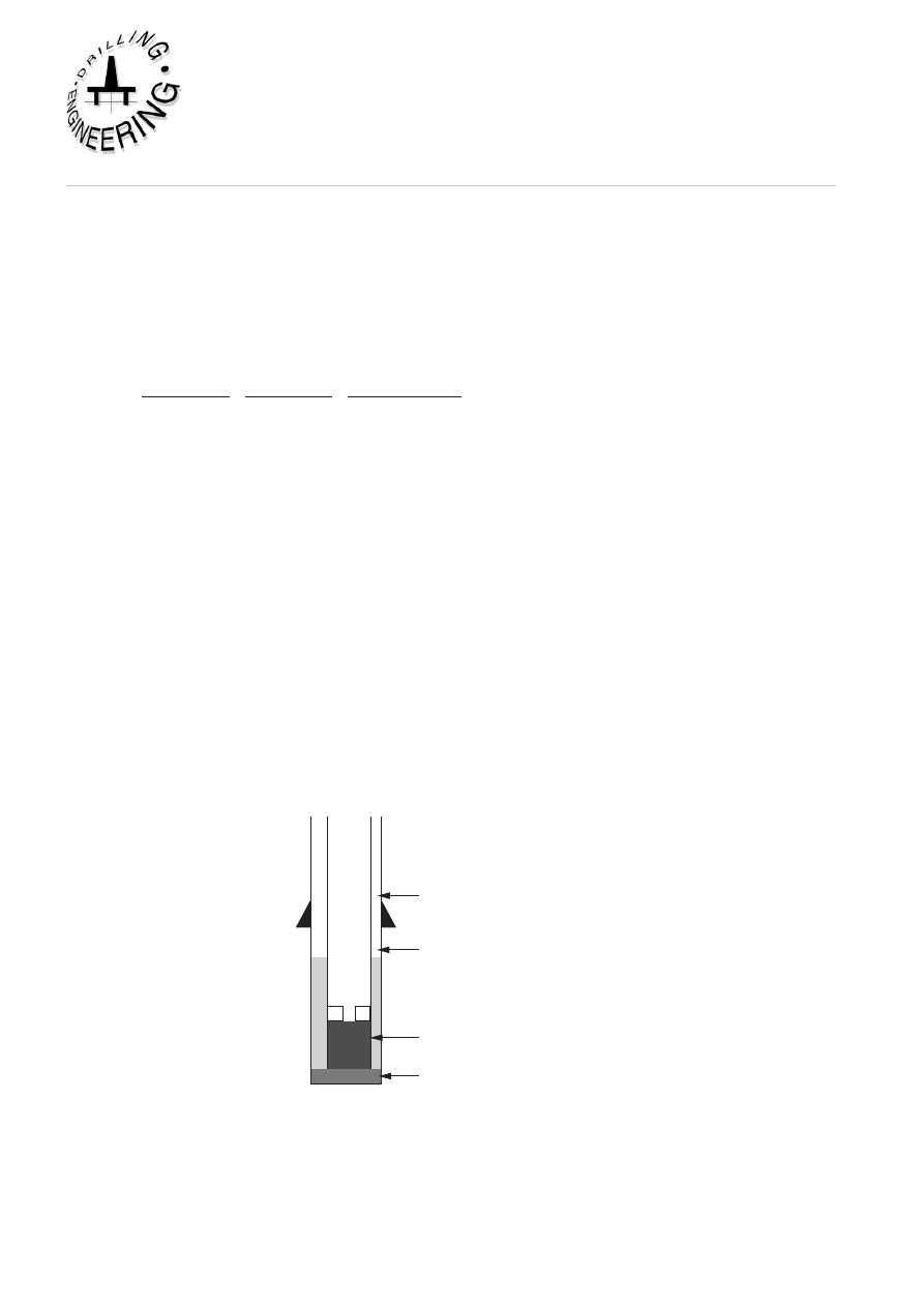
6. Duration of Operation
The duration of the operation will be used to determine the required setting time
for the cement formulation. The duration of the operation will be calculated on the
basis of the mixing rate for the cement, the pumping rate for the cement slurry and
the pumping rate for the displacing mud. An additional period of time, known as a
contingency time, is added to the calculated duration to account for any operational
problems during the operation. This contingency is generally 1 hour in duration.
The duration of the operation can be calculated from:
Duration = Vol. of Slurry + Vol. of Slurry + Displacement Vol. + Contingency Time (1hr.)
Mixing Rate Pumping Rate Displacement Rate
EXAMPLE OF CEMENT VOLuME CaLCuLaTiONS
The 9 5/8” Casing of a well is to be cemented in place with a single stage cementing
operation. The appropriate calculations are to be conducted prior to the operation.
The details of the operation are as follows:
9 5/8" casing set at:
13800',
12 1/4" hole:
13810'
13 3/8" 68 lb/ft casing set at : 6200'
TOC outside 9 5/8" casing:
3000' above shoe
Assume gauge hole, add 20% excess in open hole
The casing is to be cemented with class G cement with the following additives:
0.2% D13R (retarder)
1 % D65 (friction reducer)
Slurry density
= 15.9 ppg
Casing/Casing Annulus
Casing/Hole Annulus
(0.3132 ft
3
/ft)
Shoetrack
(0.411 ft
3
/ft)
Rathole
(0.8185 ft
3
/ft)
13 3/8 Shoe @ 6200'
TOC @ 10800'
Float Collar @ 13740'
9 5/8" Shoe @ 13800'
12 1/4" Hole @ 13810'
Figure 31
Example of Cementing Calculation

Cementing
Institute of Petroleum Engineering, Heriot-Watt University
1. Slurry Volume Between The Casing and Hole:
9 5/8" csg/ 12 1/4" hole capacity = 0.3132 ft
3
/ft
annular volume
= 3000 x 0.3132
= 939.6 ft
3
plus20% excess
=187.9ft
3
= 1127.5ft
3
=> 1128 ft
3
2. Slurry Volume Below The Float Collar:
Cap. of 9 5/8, 47 lb/ft csg
= 0.4110 ft
3
/ft
shoetrack vol.
= 60 x 0.411
Total
= 25 ft
3
3. Slurry volume in the rathole
Cap. of 12 1/4" hole
= 0.8185 ft
3
/ft
rathole vol.
= 10 x 0.8185
= 8.2 ft
3
plus 20%
= 1.6 ft
3
Total
= 9 .8 ft
3
=> 10 ft
3
Total cement slurry vol.
= 1128 + 25 + 10
= 1163 ft
3
4. Amount of cement and mixwater
Yield of class G cement for density of 15.9 ppg = 1.14 ft
3
/sk
mixwater requirements
= 4.96 gal/sk
No. of sks of cement
= 1163
= 1020 sx
1.14
Mixwater required
= 1020 x 4.96 gal
= 5059 gal
= 120 bbls
5. Amount of Additives:
Retarder D13R (0.2% by weight)
= 0.2 x 1020 x 94 (lb/sk) = 192 lb
100
Friction reducer (1.0% D65 by weight)
= 1 x 1020 x 94(lb/sk) = 959 lb
100

6. Displacement Volume:
Displacement vol.
= vol between cement head and float collar
= 0.4110 x 13740 = 5647 ft
3
= 1006 bbl
(add 2 bbl for surface line)
= 1008 bbl
For Nat. pump 12-P-160, 7" liner 97% eff, 0.138 bbl/stk
No. of strokes
= 1008
= 7300 strokes
0.138
EXERCISE 1 Cementing Calculations - Stinger Cementation
The 0" casing of a well is to be cemented to surface with class ‘C’ high early strength
cement + % Bentonite using a stinger type cementation technique. Calculate the
following for the 0" casing cementation :
a. The number of sacks of cement required (allow 100% excess in open hole).
b. The volume of mixwater required.
c. An estimate of the time taken to carry out the job.(Note: use an average mixing/
pumping time of bbls/min.)
0" Casing
: 0 - 00 ft.
0" Casing lb/ft
: 0 - 00 ft
0" Casing 1 lb/ft
: 00 - 100 ft.
" Open hole Depth
: 10 ft.
Stinger
: " 1." drillpipe
Class ‘C’ Cement + % Bentonite
Density
: 1.1 ppg
Yield
: 1. ft
/sk
Mixwater Requirements
: 1. ft/sk
EXERCISE Cementing Calculations - Two Stage Cementation
The 1 /" casing string of a well is to be cemented using class ‘G’ cement. Calculate
the following:
a. The required number of sacks of cement for a 1st stage of 00 ft. and a nd
stage of 00 ft.(Allow 0% excess in open hole)
b. The volume of mixwater required for each stage.
c. The total hydrostatic pressure exerted at the bottom of each stage of cement
(assume a 10 ppg mud is in the well when cementing).

Cementing
Institute of Petroleum Engineering, Heriot-Watt University
d. The displacement volume for each stage.
0" Casing shoe
: 100 ft
1 /" Casing
lb/ft
: 0 - 1000 ft
1 /" Casing
lb/ft
: 1000 - 000 ft.
1 1/" open hole Depth
: 00 ft.
Stage Collar Depth
: 100 ft.
Shoetrack
: 0 ft.
Cement stage 1
(000-00 ft.)
Class ‘G’
Density
: 1. ppg
Yield
: 1.1 ft
/sk
Mixwater Requirements
: 0. ft/sk
Cement stage
(100-1000 ft.)
Class ‘G’ + % bentonite
Density
: 1. ppg
Yield
: 1. ft
/sk
Mixwater Requirements
: 1. ft/sk
VOLuMETriC CaPaCiTiES
bbls/ft
ft
3
/ft
drillpipe
" drillpipe :
0.01
0.0
Casing
1 /" lb/ft :
0.10
0.1
1 /" lb/ft :
0.1
0.1
Open Hole
" Hole
0.
.
1 1/" Hole
0.
1.0
annular Spaces
" hole x 0" Casing:
0.1
1.0
1 1/" hole x 1 /" Casing:
0.1
0.
0" Casing x 0" Casing:
0.0
.0
0" Casing x 1 /" Casing:
0.11
1.01
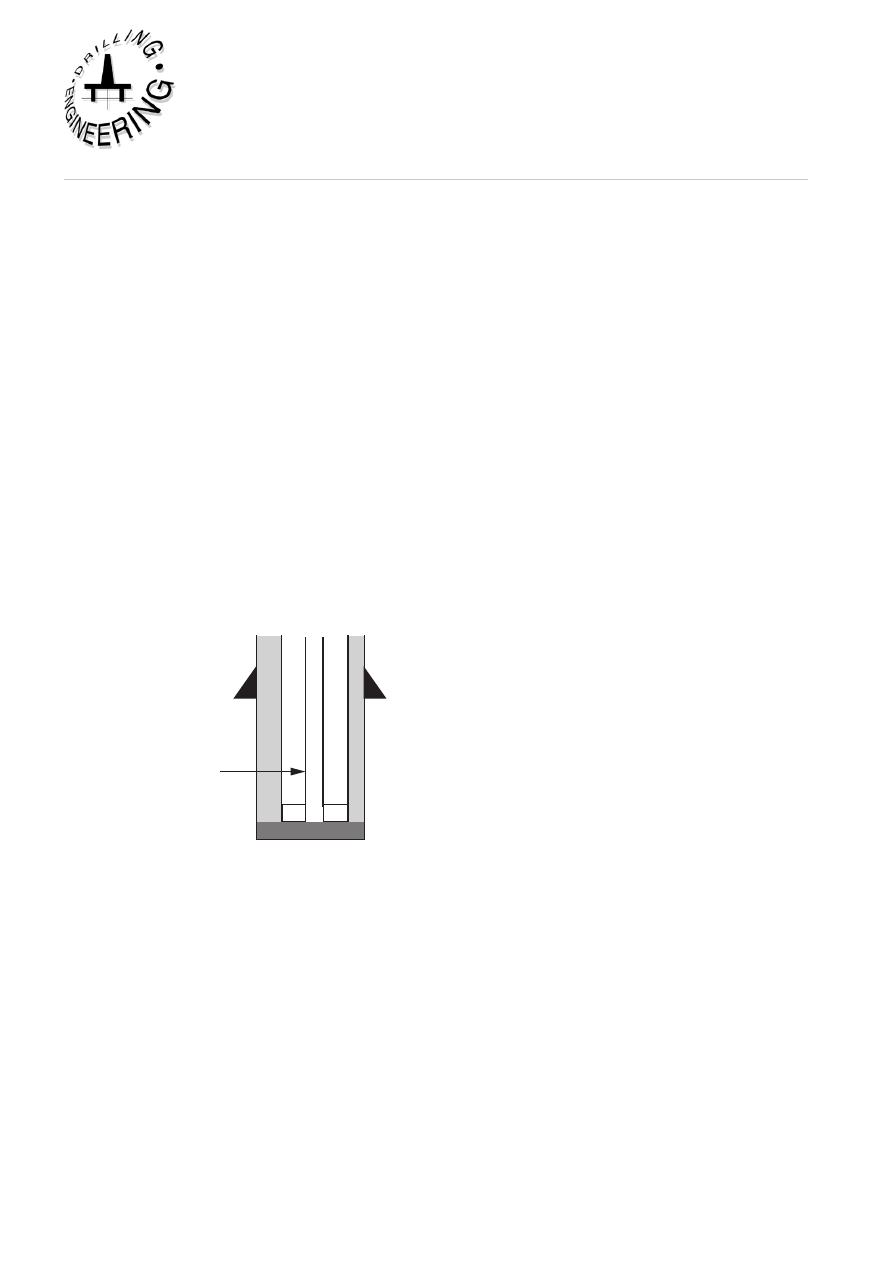
0
SOLuTiON TO EXErCiSES
Exercise 1 Cementing Calculations - Stinger Cementation
The surface (20”) casing of a well is normally cemented to surface (continue
pumping cement until it is seen at surface). In order to determine the volume of
slurry required one calculates the annular space between the conductor (30”) and the
surface string (20”) and between the surface string and the openhole. The volume
of rathole is added to the above and the slurry volume is translated via the yield of
the cement recipe to the number of sacks of cement required for the entire job.
The volume of mixwater required is specified in the slurry recipe in terms of cu
ft. per sack of cement and will be determined on the basis of a required cement
strength, setting time and allowable free water content.
The time required for the cement job will include the mixing and pumping time
(assuming that the slurry is not batch mixed), the time to displace the cement from
the cement stinger (since this type of job would normally be carried out using a
stinger cementation technique) and 1 hr. contingency time to allow for operational
problems during the job. The operation duration will be used to design the slurry so
that the cement is set as soon as possible after the job is complete.
400'
1500'
1530'
26" Hole
5" d.p
30"
a. No. sxs cement
Slurry volume between the 20" casing and 30" casing:
20" casing/30" casing capacity
= 2.0944 ft
3
/ft
annular volume
= 400 x 2.0944
= 838 ft
3
Slurry volume between the casing and hole:
20" csg/ 26" hole capacity
= 1.5053 ft
3
/ft
annular volume
= 1100 x 1.5053
= 1656 ft
3
plus100% excess
= 1656 ft
3
Total
= 3312 ft
3

Cementing
1
Institute of Petroleum Engineering, Heriot-Watt University
Slurry volume in the rathole
Cap. of 26" hole
= 3.687 ft
3
/ft
rathole vol.
= 30 x 3.687
= 111 ft
3
plus 100%
= 111 ft
3
Total
= 222 ft
3
TOTAL SLURRY VOL. :
= 4372 ft
3
Yield of class C cement for density of 13.1 ppg
= 1.88 ft
3
/sk
TOTAL No. SXS CEMENT :
4372/1.88 = 2326 sxs
b. Mixwater Requirements
Mixwater requirements for class C cement with 6% Bentonite
= 1.36 ft
3
/sk
Mixwater required
= 2326 x 1.36
= 3163 ft
3
c. Displacement Time
Total Displacement time = Time to mix and pump cement + time to displace
cement
Total Volume of Cement
= 4372 ft
3
= 779 bbl
Displacement vol. = vol to displace down drillipipe leaving 1 bbl under displaced
d.p. capacity
= 0.01776 bbl/ft
Displacement to 1500 ft
= 0.01776 x 1500
= 26.6 bbl
(underdisplace by 1 bbl )
= 25.6 bbl
Total Volume to mix and displace = 779 + 25.6 = 804.6 bbls
Total time @ 5 bbl/min
= 804.6/5
= 160.9 = 2.7 hrs
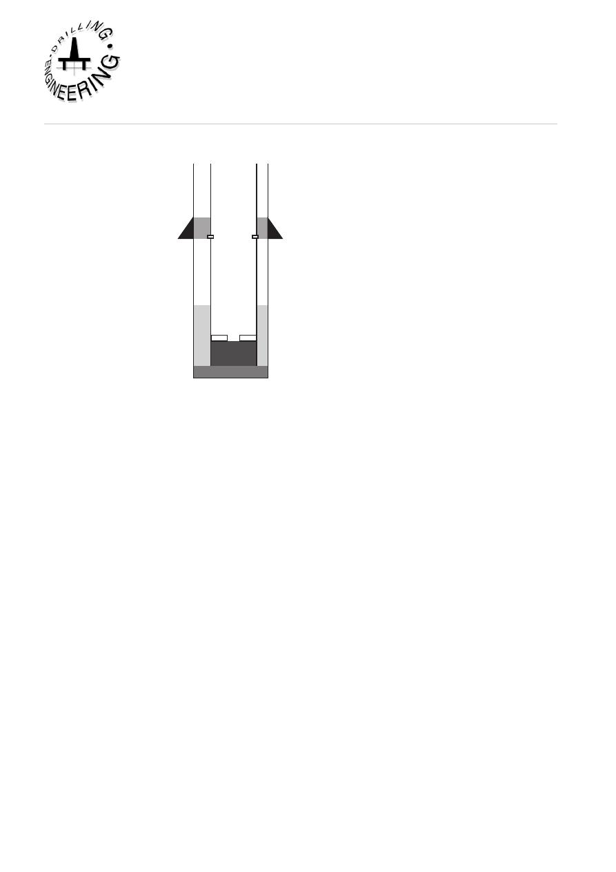
Exercise 2 Cementation Calculations - Two Stage Cementation
1000'
1500'
6300'
6940'
7030'
7000'
77 lb/ft
72 lb/ft
20" Shoe
17 1/2" Hole
TOC
a. No. sxs cement
Stage 1:
Slurry volume between the casing and hole:
13 3/8" csg/ 17 1/2" hole capacity
= 0.6946 ft
3
/ft
annular volume
= 700 x 0.6946
= 486 ft
3
plus20% excess
= 97 ft
3
Total
= 583 ft
3
Slurry volume below the float collar:
Cap. of 13 3/8, 72 lb/ft csg
= 0.0.8314 ft
3
/ft
shoetrack vol.
= 60 x 0.8314
Total
= 50 ft
3
Slurry volume in the rathole
Cap. of 17 1/2" hole
= 1.6703 ft
3
/ft
rathole vol.
= 30 x .6703
= 50.11 ft
3
plus 20%
= 10.02 ft
3
Total
= 60 ft
3
TOTAL SLURRY VOL. STAGE 1 :
= 693 ft
3
Yield of class G cement for density of 15.9 ppg = 1.18 ft
3
/sk
TOTAL No. SXS CEMENT STAGE 1:
693/1.18 = 587 sxs

Cementing
Institute of Petroleum Engineering, Heriot-Watt University
Stage 2:
20" csg/ 13 3/8" csg
= 1.0194 ft
3
/ft
annular volume
= 500 x 1.0194
= 508 ft
3
TOTAL SLURRY VOL. STAGE 2 :
508 ft
3
Yield of class G cement for density of 13.2 ppg
= 1.89 ft
3
/sk
TOTAL No. SXS CEMENT STAGE 2:
508/1.89 = 269 sxs
b. Mixwater Requirements
Stage 1:
mixwater requirements for class G cement for density of 15.9 ppg
= 0.67 ft
3
/sk
Mixwater required
= 587 x 0.67
= 393 ft
3
Stage 2:
mixwater requirements for class G cement for density of 13.2 ppg
= 1.37 ft
3
/sk
Mixwater required
= 270 x 1.37
= 370 ft
3
c. Hydrostatic Head
Stage 1:
Mud Hydrostatic (0 - 6300 ft) + Cement Hydrostatic (6300 - 7030 ft)
= 6300 x 10 x 0.052 + 730 x 15.9 x 0.052
= 3880 psi
Stage 2:
Mud Hydrostatic (0 - 1000 ft) + Cement Hydrostatic (1000 - 1500 ft)
= 1000 x 10 x 0.052 + 500 x 13.2 x 0.052
= 863 psi
A knowledge of the hydrostatic pressure exerted by the cement slurry when it is
place will ensure that the formation fracture pressure will not be exceeded during
the cement job.

d. Displacement Volumes
Stage 1:
Displacement vol. = vol between cement head and float collar
= 0.1463 x 1000 (77 lb/ft casing) + 0.148 x 5940 (72 lb/ft casing)
= 1025 bbl
(add 2 bbl for surface line)
= 1027 bbl
Stage 2:
Displacement vol. = vol between cement head and stage collar
= 0.1463 x 1000 (77 lb/ft casing) + 0.148 x 500 (72 lb/ft casing)
= 220 bbl
(add 2 bbl for surface line)
= 222 bbl