
MAXIMUM POWER TRANSFER THEOREM:
“In any circuit the maximum power is transferred to the load when the load resistance is equal to the
source resistance. The source resistance is equal to the Thevenin’s equal resistance
”.
Procedure:
Step 1:
2.
Measure the Power across the load resistor by considering all the sources in the network.
Step 2: Finding Thevenin’s Resistance(R
TH
)
1.
Open the load terminals and replace all the sources with their internal impedances.
2.
Measure the impedance across the open circuited terminal which is known as Thevenin’s
Resistance.
Step 3: Finding Thevenin’s Voltage(V
TH
)
1.
Open the load terminals and measure the voltage across the open circuited terminals.
2.
Measured voltage will be known as Thevenin’s Voltage.
Step 4: Measuring Power for different Load Resistors
1.
V
TH
and R
TH
are connected in series with the load.
2.
Measure power across the load by considering R
L
=R
TH
.
3.
Measure power by using P =
.
4.
Verify the power for different values of load resistors(i.e. R
L
>R
TH
and R
L
<R
TH
)
Power measured from the above steps results in maximum power dissipation when R
L
=R
TH
.
Hence Maximum Power Transfer Theorem is verified.
1.
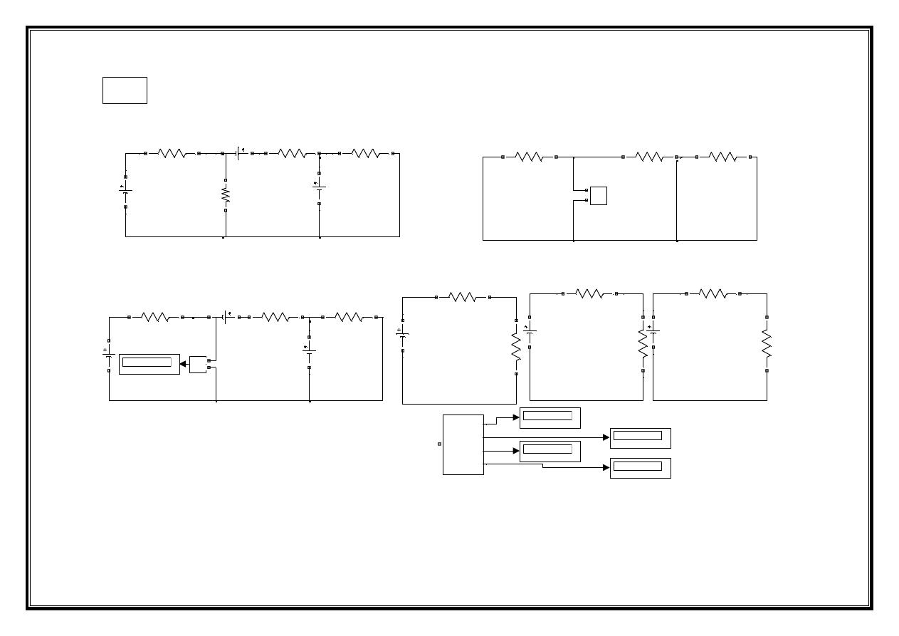
Make the connections as shown in the circuit diagram by using MATLAB / Simulink.
Experiment 3
V1=10V
R1=10 Ohms
V2=15V
R2=12 Ohms
V3=8V
R3=1 Ohm
RL=5.4545 Ohms
Step 1 : By Considering All Sources In The Network
MAXIMUM POWER T RANSFER THEOREM
Open Circuit Voltage Vth = 2.273V
Thevenin's Resistance = 5.4545Ohms
Power acroos the load in the original circuit =0.2367 Watts
Power across Load circuit when RL=Rth=5.4545 is = 0.2368 Watts
Power across Load when RL=5 Ohms is =0.2364 Watts
Power across Load when RL=6 Ohms is = 0.2367 Watts
Vth=2.273V
Rth=5.4545 Ohms
Step 4 : Power in Load Resistors with RL=RTH, RL>RTH, RL<RT H
RL=5.4545 Ohms
R1=10 Ohms
V2=0V
R2=12 Ohms
V3=0V
Step 2: Finding Thevenin's Resistance
V1=0V
R3=1 Ohm
V1=10V
R1=10 Ohms
V2=15V
R2=12 Ohms
V3=8V
R3=1 Ohms
Step 3 : Finding Thevenin's Voltage
Open circuited RL
Vth=2.273V
Rth=5.4545 Ohms
RL=6 Ohms
Vth=2.273V
Rth=5.4545 Ohms
RL=5 Ohms
Power across Load when RL=6 Ohms
Power across Load when RL=5 Ohms
Power acroos load when RL=RT H
Power in Original Circuit
Co ntinuous
powe rgui
v
+
-
Out1
Out2
Out3
Out4
Conn1
Power Measurements for different resistors
Z
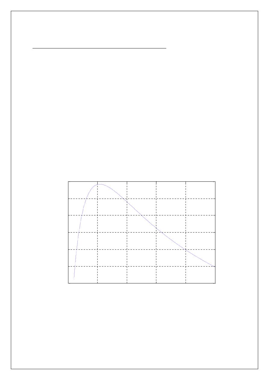
M-File Program for Maximum Power Transfer Theorem:
clc;
close
all
;
clear
all
;
v=input(
'Enter the Voltage in Volts :'
);
rth=input(
'Enter the value of Thevenins Resistance:'
);
rl=1:0.0001:12;
i=v./(rth+rl);
p=i.^2.*rl;
plot(rl,p);
grid;
title(
'Maximum Power'
);
xlabel(
'Load Resistance in Ohms------->'
);
ylabel(
'Power Dissipation in watts-------->'
);
0
5
10
15
20
25
0.12
0.14
0.16
0.18
0.2
0.22
0.24
Maximum Power
Load Resistance in Ohms------->
P
o
w
e
r
D
is
s
ip
a
ti
o
n
i
n
w
a
tt
s
--
--
--
--
>