Distribution systems
Second classElectrical engineering
syllabus
Introduction•Classification of Distribution System
•Comparison among Distribution Systems
•Overhead versus underground system –
Methods of Connection:
•A.C. Distribution systems
•D.C. Distribution
•Type of D.C Distributions:
•Methods of obtaining 3-wire d.c.system
syllabus
•A.C Distributors:•Single-phase and three-phase distributor
Requirements of a distribution system
•Design considerations' in distribution system
•Connection schemes of distribution system
•Power Factor Improving
•Distribution System Overcorrect Protection:
•Fuses, Relays, Circuit Breakers,
•Protection of Distribution Lines
•Protection of Distribution Transformers and Distribution Capacitors
sources
ELECTRICAL TECHNOLOGY
Chapter 40
D.C. transmission and distribution.
Chapter 41
A.C. transmission and distribution.
POWER SYSTEMS PROTECTION
Power system
Power system consists of three parts• Generation system
• Transmission system
• Distribution system
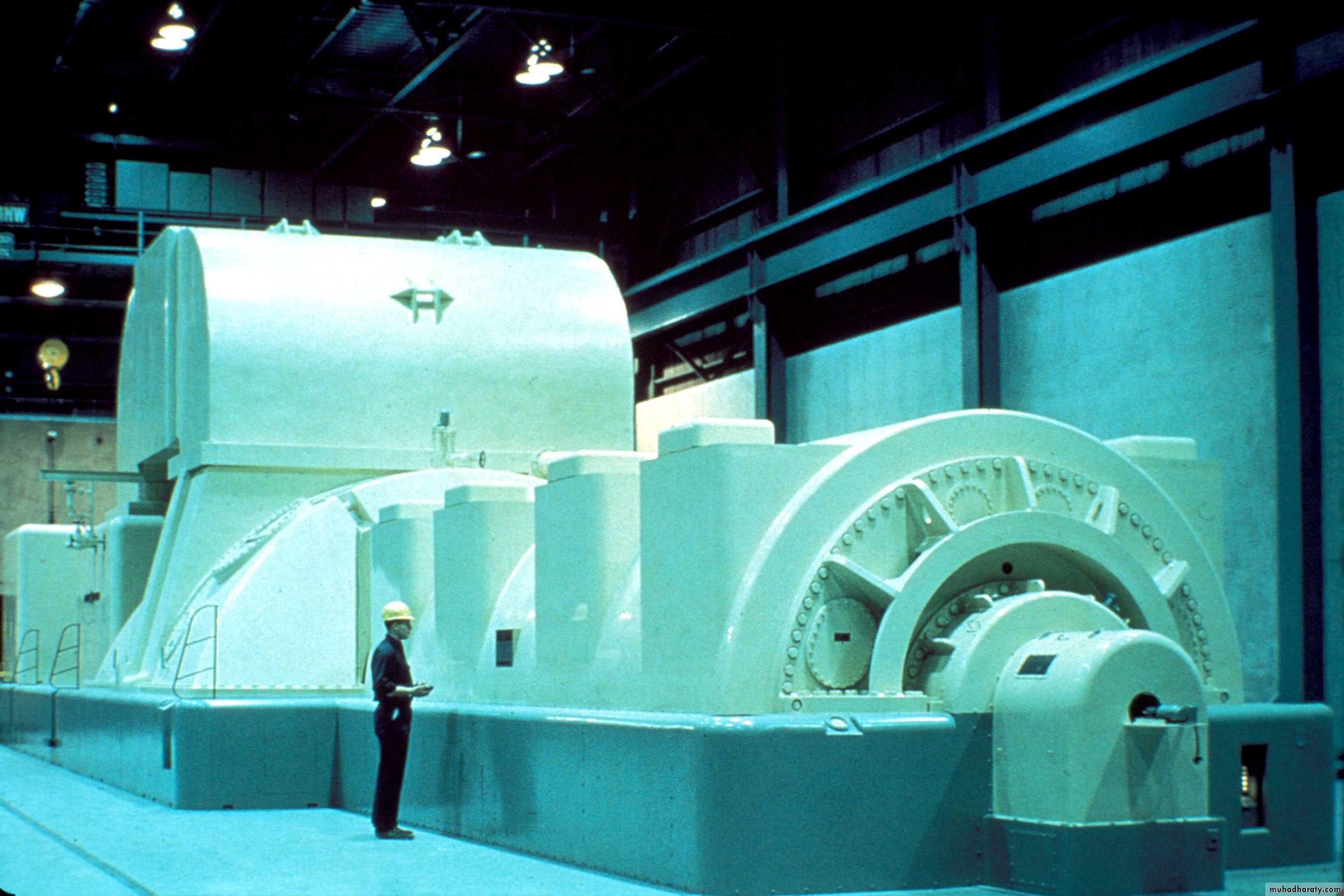
generation
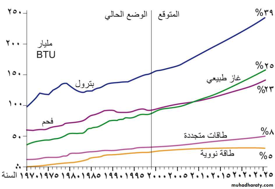
Types of a power plant :
DieselGas
coal
Wind power
Steam
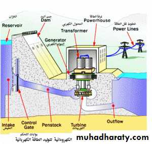
Water stations
Nuclear
Transmission system
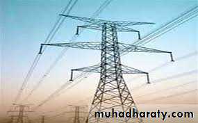
power is conveyed by bare conductors of copper or aluminium which are strung between wooden or steel poles erected at convenient distances along a route. The bare copper or aluminium wire is fixed to an insulator which is itself fixed onto a cross-arm on the pole. The number of cross-arms carried by a pole depends on the number of wires it has to carry. Line supports consist of (i) pole structures and(ii) tower.
Poles which are made of wood, reinforced concrete or steel are used up to 66 kV
Whereas steel towers are used for higher voltages.
The underground system employs insulated cables which may be single, double or triple-core
1-Step-up transformer2-transmission tower
Good power system
A good system whether overhead or underground should fulfil the following requirements :1. The voltage at the consumer’s premises must be maintained within ± 4 or ± 6% of the
declared voltage, the actual value depending on the type of load*.
2. The loss of power in the system itself should be a small percentage (about 10%) of the
power transmitted.
3. The transmission cost should not be unduly excessive.
4. The maximum current passing through the conductor should be limited to such a value as
not to overheat the conductor or damage its insulation.
5. The insulation resistance of the whole system should be very high so that there is no undue
leakage or danger to human life.
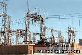
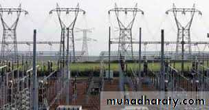
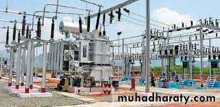
1-Sub-station2-step-down transformer
Why a.c. not d.c.
There are many sound reasons for producing power in the form of alternating current rather than direct current.(i) It is possible, in practice, to construct large high-speed a.c. generators of capacities up to 500 MW. Such generators are economical both in the matter of cost per kWh of electric energy produced as well as in operation. Unfortunately, d.c. generators cannot be built of ratings higher than 5 MW because of commutation trouble. Moreover, since they must operate at low speeds, it necessitates large and heavy machines.
(ii) A.C. voltage can be efficiently and conveniently raised or lowered for economic transmission and distribution of electric power respectively. On the other hand, d.c. power has to be generated at comparatively low voltages by units of relatively low power ratings. As yet, there is no economical method of raising the d.c. voltage for transmission and lowering it for distribution.
Distribution systemdefinitions
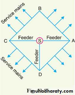
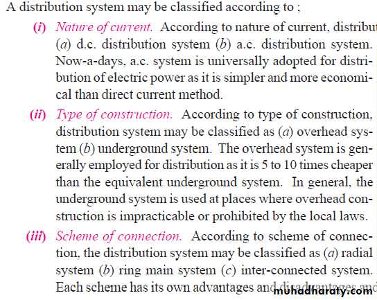
Classification of distribution systems
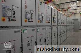
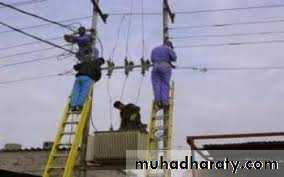
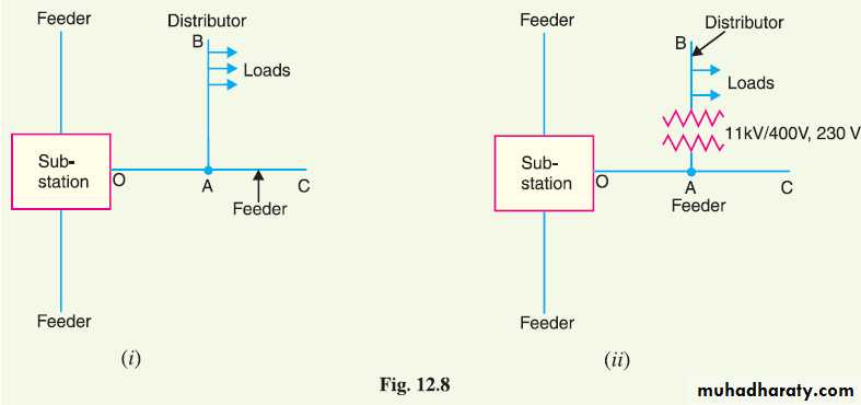
1-sub-station( secondary Distribution ) 2-11kv_400v transformer (primary distribution)
H.W
اذكر اسماء محطات التوليد في مدينة الموصل
ماسم محطة التوليد التي تجهز مدينة كركوك بالطاقة الكهربائية ؟ وماهي قدرة المحطة
ماهو اكثر نوع من انواع محطات التوليد تستخدم في الدول العربية ؟ اذكر امثلة
ماهي اسماء اشهر الشركات العالمية المتخصصة ببناء محطات التوليد الكهربائية
اذكر اسم اشهر شركة عربية متخصصة بانظمة القدرة الكهربائية
ماهي سرعة المولد الكهربائي في محطات التوليد
ماحجم قدرة توليد اي محطة كهربائية ؟
Connection schemes of distribution system
Radial system
Radial connection limitation
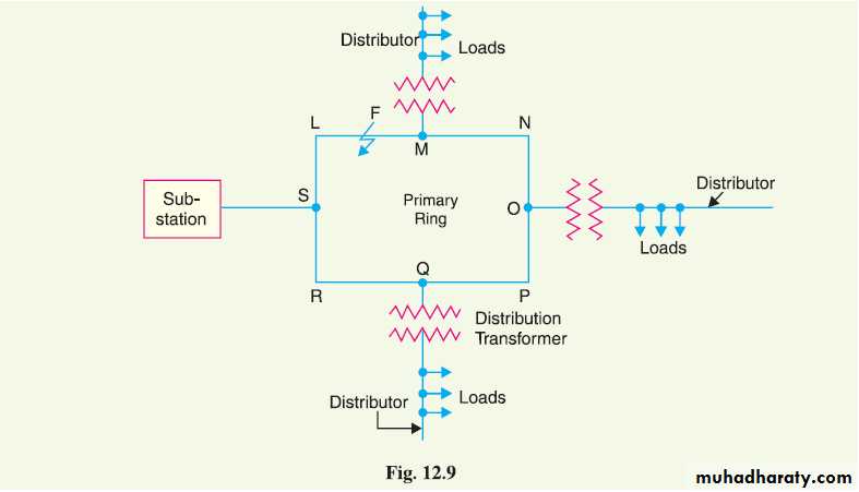
Ring system advantages
Second type of distribution system connection
Single line diagram or ring main system for a.c. distribution
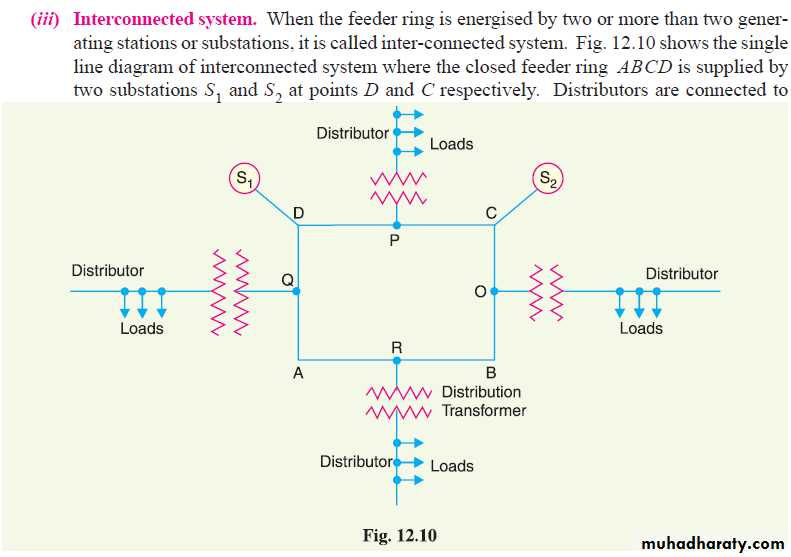
third type of connection
Inter connected system advantages
d.c. distribution
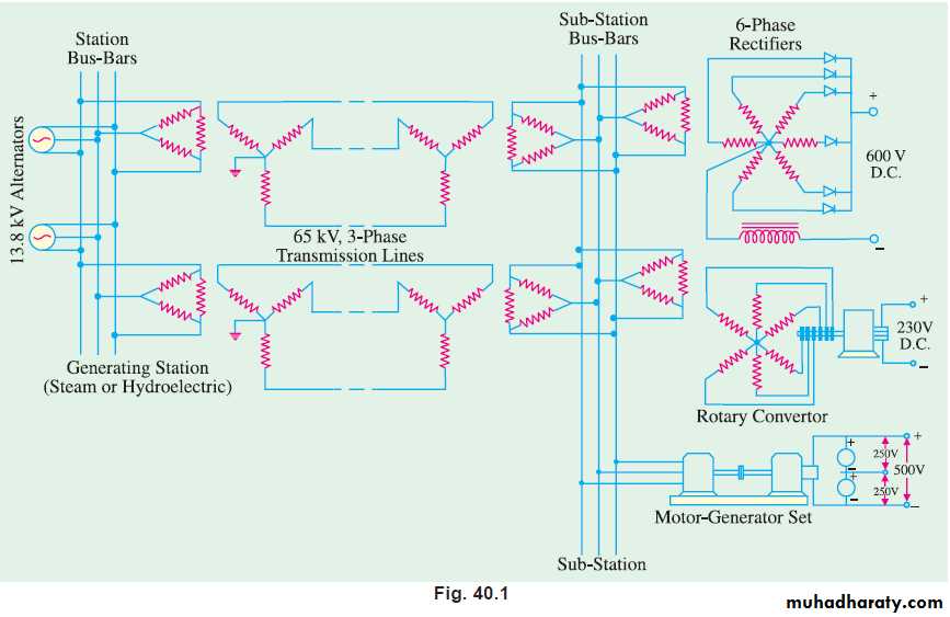
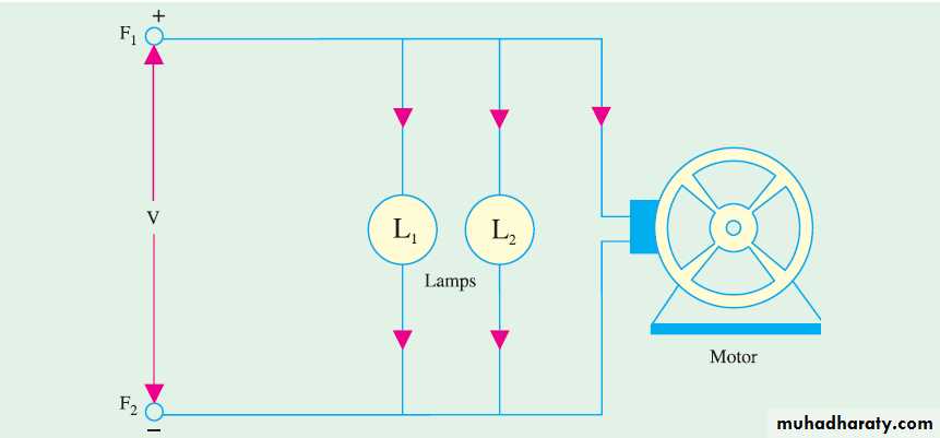
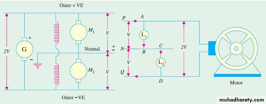
D.c. supply is required for operation of variable speed machinery (i.e.,d.c. motors) for this purpose a.c. power is converted into d.c. power at sub-station by using converting e.g., mercury arc rectifiers rotary convertors and motors generator sets. The d.c. supply form substation may be obtained in the form of (i) 2-wire or (ii) 3-wire for the distribution.
The 2-wire system when used for transmission purposes, has much lower efficiency and economy as compared to the 3-wire system as shown later.
Fig. 40.1 shows a typical power system for obtaining d.c. power from a.c. power.
Two-wire and three wire systems
Methods of Feeding a Distributor
Different methods of feeding a distributor are given below :1. feeding at one end
2. feeding at both ends with equal voltages
3. feeding at both ends with unequal voltages
4. feeding at some intermediate point
In adding, the nature of loading also varies such as
(a) concentrated loading (b) uniform loading (c) combination of (a) and (b).
D.C. Distributor Fed at One End
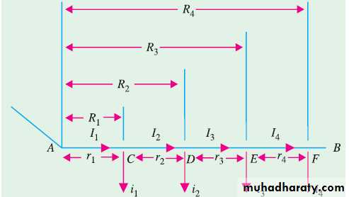
total drop in the distributor is
= i1r1 + i2(r1 + r2) + i3(r1 + r2 + r3) + ...... i1R1 + i2R2 + i3 R3 + .......=
The value of the drop at point E== i1R1 + i2R2 + i3R3 + R3(i4 + i5 + i6 + .....)*
Uniformly Loaded Distributor
Total drop in the distributor AB = ½ (I * R )
where i × l = I total current entering at point Ar × l = R the total resistance of distributor AB.
NOTE:
total drop is equal to that produced by the
whole of the load assumed concentrated at the middle point.
IF THE distributor is fed at both ends A and B with equal voltages. In that case,the point of minimum potential is obviously the middle point.
example 40.2
Example 40.2. A uniform 2-wire d.c. distributor 200 meters long is loaded with 2 amperes/meter. Resistance of single wire is 0.3 ohm/kilometer. Calculate the maximum voltage drop if the distributor is fed (a) from one end (b) from both ends with equal voltages.Solution. (a) Total resistance of the distributor is R = 0.3 × (200/1000) = 0.06
Total current entering the distributor is I = 2 × 200 = 400 A
Total drop on the whole length of the distributor is ½ IR=2 × 400 × 0.06 = 12 V
(b) Since distributor is fed from both ends, total voltage drop is 1/8 IR = 8 × 400 × 0.06 = 3 VAs explained in Art. 40.6 the voltage drop in this case is one-fourth of that in case (a) above.
Example 40.3 p.1544 electrical technology
A 2-wire d.c. distributor AB is 300 metres long. It is fed at point A. The variousloads and their positions are given below :
At point distance from A in metres concentrated load in A
Let ‘A’ be cross sectional area of distributor
As proved in Art. 40.5 total drop over the distributor isν = i1R1 + i2R2 + i3R3 + i4 R4 —for one conductor
= 2(i1R1 + i2R2 + i3R3 + i4R4) —for two conductors
where R1 = resistance of AC = 1.78 × 10−8 × 40/A
R2 = resistance of AD = 1.78 × 10−8 × 100/A
R3 = resistance of AE = 1.78 × 10−8 × 150/A
R4 = resistance of AF = 1.78 × 10−8 × 250/A
Since ν = 10 V, we get
10 =2*1.78*(30*40+40*100+100*150+50*250)/100000000*A
=2*1.78*10-8*32.700/A
A = 3.56 × 327 × 10−7 m2 = 1,163 cm2
Example 40.6 p.1580
The resistance of two conductors of a 2-conductor distributor shown in Fig. 39.15 is 0.1 Ω per 1000 m for both conductors. Find (a) the current supplied at A (b) the current supplied at B (c) the current in each section (d) the voltages at C, D and E. Both A and B are maintained at 200 V. (Electrical Engg. Grad. I.E.T.E.)
Solution. The distributor along with its tapped currents is shown in Fig. 40.15. Let the current distribution be as shown. Resistance per metre double is = 0.1/1000 = 10−4 Ω. The total drop over the whole distributor is zero because it is fed at both ends by equal voltages
∴ 10−4 [500i + 700 (i − 50) + 300 (i − 150) + 250 (i − 300)] = 0
or 1750i = 155,000 or i = 88.6 A
This gives the current distribution shown in Fig. 40.16.
(a) IA = 88.6 A (b) IB = −211.4 A
(c) Current in section AC = 88.6 A; Current in CD = (88.6 − 50) = 38.6 ACurrent in section DE = (31.6 − 100) = − 61.4 A
Current in EB = (− 61.4 − 150) = − 211.4 A
(d) Drop over AC = 10−4 × 500 × 88.6 = 4.43 V; Drop over CD = 10−4 × 700 × 38.6 = 2.7 V
Drop over DE = 10−4 × 300 × − 61.4 = −1.84 V
∴ Voltage at C = 200 − 4.43 = 195.57 V
Voltage at D = (195.57 − 2.7) = 192.87 V,
Voltage at E = 192.87 − (−1.84) = 194.71 V
Distributor Fed at Both Ends with Unequal Voltages
This case can be dealt with either by
taking moments (in amp-m) about the two ends and then making a guess about the point of minimum potential or
by assuming a current x fed at one end and then finding the actual current distribution.
Example 40.8
Uniform Loading with Distributor Fed at Both Ends
Consider a distributor PQ of length l units of length, havingresistance per unit length of r ohms and with loading per unit
length of i amperes. Let the difference in potentials of the two
feeding points be ν volts with Q at the lower potential. The
procedure for finding the point of minimum potential is as follows:
Let us assume that point of minimum potential M is situated
at a distance of x units from P. Then drop from P to M
is = irx2/2 volts (Art. 40.6)
Example 40.10
Uniform Loading with Distributor Fed at Both Ends
Since the distance of M from Q is (l − x), the drop from Q toM is = IR(L-X)^2/2
Since potential of P is greater than that of Q by ν volts,
∴Irx^2/2=ir(l-x)^2/2+v
X=l/2+v/irl
L= length
I = ampere per unit length
r = resistance/meter
Concentrated and Uniform Loading with Distributor Fed at One End
Such cases are solved in two stages. First, the drop at any point due to concentrated loading is
found. To this add the voltage drop due to uniform loading as calculated from the relation.
Ir(lx-x^2)/2

