14. Turning Moment Diagrams and Flywheel:
14.1 Turning moment diagram:
The turning moment diagram (also known as crank
representation of the turning moment
Figure 1.
The total area under the curve represents the work done by the crankshaft during the cycle.
If the resisting torque is constant, this is represented by the line
the mean engine torque. Between points
torque and the crank shaft accelerates, the area
energy supplied during that time. Similarly, between
than the resisting torque and the crankshaft decelerates, the area
insufficiency in energy available during that time.
At the points of intersection, A, B, etc., the engine and load
is no acceleration or deceleration of the flywheel; hence the speed is a maximum or
minimum at these points.
14.2 Flywheel:
A flywheel is a device to control the variations in speed during each cycle of an engine
serves as a reservoir, which stores energy during the period when the supply of energy is
more than the requirement, and releases it during the period when the requirement of
energy is more than the supply. For the first period the flywheel speed increases and for
the second period the flywheel speed decreases. Therefore, the flywheel keeps the speed of
the engine within specified limits during each cycle.
14.3 Fluctuation of Energy:
The variations of energy above and below the mean resisting torque line, Figure
called fluctuations of energy.
14.3.1 Maximum Fluctuation of Energy:
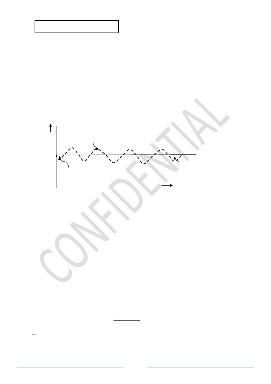
A turning moment diagram of a multi
2. The horizontal line AG represents the mean torque line. Let a
above AG line and a
2
, a
4
, and a
6
be the areas below
quantity of energy which is either added or subtracted from the energy of the moving parts
of the engine.
Figure 1
Page 1
. Turning Moment Diagrams and Flywheel:
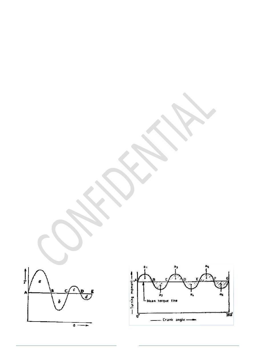
The turning moment diagram (also known as crank-effort diagram) is the graphical
representation of the turning moment or crank effort for various positions of the crank,
The total area under the curve represents the work done by the crankshaft during the cycle.
If the resisting torque is constant, this is represented by the line AE, which also represents
n engine torque. Between points A and B, the engine torque exceeds the resisting
torque and the crank shaft accelerates, the area a of the loop representing the excess
energy supplied during that time. Similarly, between B and C, the engine torque is less
than the resisting torque and the crankshaft decelerates, the area b representing the
insufficiency in energy available during that time.
, etc., the engine and load torques are equal, so that there
is no acceleration or deceleration of the flywheel; hence the speed is a maximum or
A flywheel is a device to control the variations in speed during each cycle of an engine
voir, which stores energy during the period when the supply of energy is
more than the requirement, and releases it during the period when the requirement of
For the first period the flywheel speed increases and for
nd period the flywheel speed decreases. Therefore, the flywheel keeps the speed of
the engine within specified limits during each cycle.
The variations of energy above and below the mean resisting torque line, Figure
Maximum Fluctuation of Energy:
A turning moment diagram of a multi-cylinder engine is shown by a wavy curve in Figure
represents the mean torque line. Let a
1
, a
3
, and a
be the areas below AG line. These areas
quantity of energy which is either added or subtracted from the energy of the moving parts
Figure 2
effort diagram) is the graphical
or crank effort for various positions of the crank,
The total area under the curve represents the work done by the crankshaft during the cycle.
, which also represents
, the engine torque exceeds the resisting
of the loop representing the excess
, the engine torque is less
representing the
equal, so that there
is no acceleration or deceleration of the flywheel; hence the speed is a maximum or
A flywheel is a device to control the variations in speed during each cycle of an engine. It
voir, which stores energy during the period when the supply of energy is
more than the requirement, and releases it during the period when the requirement of
For the first period the flywheel speed increases and for
nd period the flywheel speed decreases. Therefore, the flywheel keeps the speed of
The variations of energy above and below the mean resisting torque line, Figure 1, are
cylinder engine is shown by a wavy curve in Figure
, and a
5
be the areas
represent some
quantity of energy which is either added or subtracted from the energy of the moving parts

Page 2
If the energy of the flywheel at point A = U,
Energy at B = U + a
1
Energy at C = U + a
1
– a
2
Energy at D = U + a
1
– a
2
+ a
3
Energy at E = U + a
1
– a
2
+ a
3
– a
4
Energy at F = U + a
1
– a
2
+ a
3
– a
4
+ a
5
Energy at G = U + a
1
– a
2
+ a
3
– a
4
+ a
5
– a
6
= Energy at A
Let us now suppose that the greatest of these energies is at B and least at E. Therefore,
Maximum energy in the flywheel = U + a
1
Minimum energy in the flywheel = U + a
1
– a
2
+ a
3
– a
4
∴ Maximum fluctuation of energy = Max. energy – Min. energy
= (U + a
1
) – (U + a
1
– a
2
+ a
3
– a
4
)
= a
2
– a
3
+ a
4
14.3.2 Coefficient of Fluctuation of Energy:
It may be defined as the ratio of the maximum fluctuation of energy to the workdone per
cycle.
=
The workdone per cycle may be obtained by using the following two relations:
1. Workdone per cycle = T
mean
*
θ
where
T
mean
= Mean torque, and
θ = Angle turned (in radians), in one revolution.
2. Workdone / cycle = P * 60 / N
where
P = Power in Watts, and
N = Speed in rpm
14.3.3 Coefficient of Fluctuation of Speed:
The difference between the maximum and minimum speeds during a cycle is called the
maximum fluctuation of speed. The ratio of the maximum fluctuation of speed to the mean
speed is called the coefficient of fluctuation of speed.
Let N1 and N2 = Maximum and minimum speeds in rpm during the cycle, and
N = mean speed in rpm
∴
=
−
=
−

Page 3
14.4 Energy Stored in a Flywheel:
We know that when a flywheel absorbs energy, its speed increases and when it gives up
energy, its speed decreases.
Let
m = Mass of the flywheel in kg.
k = Radius of gyration of the flywheel, in meters.
I = Mass moment of inertia of the flywheel about its axis of rotation in kg m
2
.
= m * k
2
N
1
and N
2
= Maximum and minimum speeds during the cycle in rpm.
ω
1
and ω
2
= Maximum and minimum angular speeds during the cycle in rad/s.
ω = Mean angular speed during the cycle in rad/s. = (ω
1
+ω
2
)/2
We know that the mean kinetic energy of the flywheel,
=
1
2 ∗
=
1
2
As the speed of the flywheel changes from ω
1
to ω
2
, the maximum fluctuation of energy,
= . . . − . . =
1
2
(
−
) = ∗ (
−
)
= ∗
(
−
)
=
= 2 ∗
Example 1: A flywheel of an engine has a mass 6.5 tons and the radius of gyration is 1.8
m. It is found from turning moment diagram that the fluctuation of energy is 56 kJ. If the
mean speed of the engine is 120 rpm, find the maximum and minimum speeds.
Solution:
ω = 2π*120/60 = 12.566 rad / s
=
∴
=
=
56000
6500 ∗ 1.8
∗ 12.566
= 0.016839
C
S
= (ω
1
– ω
2
) / ω
ω
1
– ω
2
= 0.016509 * ω = 0.2116
rad / s
and
ω
1
+ ω
2
= 2 * ω = 25.132
rad / s
∴ ω
1
= 12.672 rad / s
and ω
2
= 12.46 rad / s
Example 2: The flywheel of a steam engine has a radius of gyration of
kg. The starting torque of the steam engine is
Determine: (a) the angular acceleration of the flywheel,
flywheel after 10 seconds from the start.
Solution:
I = m * k
2
= 2500
a) Angular acceleration of the flywheel
Let
α = angular acceleration of the flywheel
We know that T = I * α
∴ α = T / I = 1500
b) Kinetic energy of the flywheel
First of all, let us find out the angular speed of the flywheel after
start (i.e. from rest), assuming uniform acceleration.
Let
ω
1
= Angular speed at rest =
ω
2
= Angular speed after
t = Time in seconds
ω
2
= ω
1
+ α * t =
∴ ℎ ℎ
Example 3: The turning moment diagram for a petrol engine is drawing to the following
scales: turning moment 1 mm = 5
diagram repeats itself at every half-revolution of the engine and the areas above and below
the mean turning moment line, taking in order, are
rotating parts are equivalent to a mass of
Determine the coefficient of fluctuation of speed when the engine runs at
Page 4
The flywheel of a steam engine has a radius of gyration of 1 m and mass
kg. The starting torque of the steam engine is 1500 Nm and may be assumed constant.
a) the angular acceleration of the flywheel, and (b) the kinetic energy of the
seconds from the start.
2500 * 1
2
= 2500 kg m
2
Angular acceleration of the flywheel
= angular acceleration of the flywheel
1500 / 2500 = 0.6 rad/s
2
Kinetic energy of the flywheel
First of all, let us find out the angular speed of the flywheel after 10 seconds from the
start (i.e. from rest), assuming uniform acceleration.
= Angular speed at rest = 0
= Angular speed after 10 sec, and
= Time in seconds
t = 0 + 0.6 * 10 = 6 rad/s
=
1
2
=
1
2 ∗ 2500 ∗ 36 = 45000
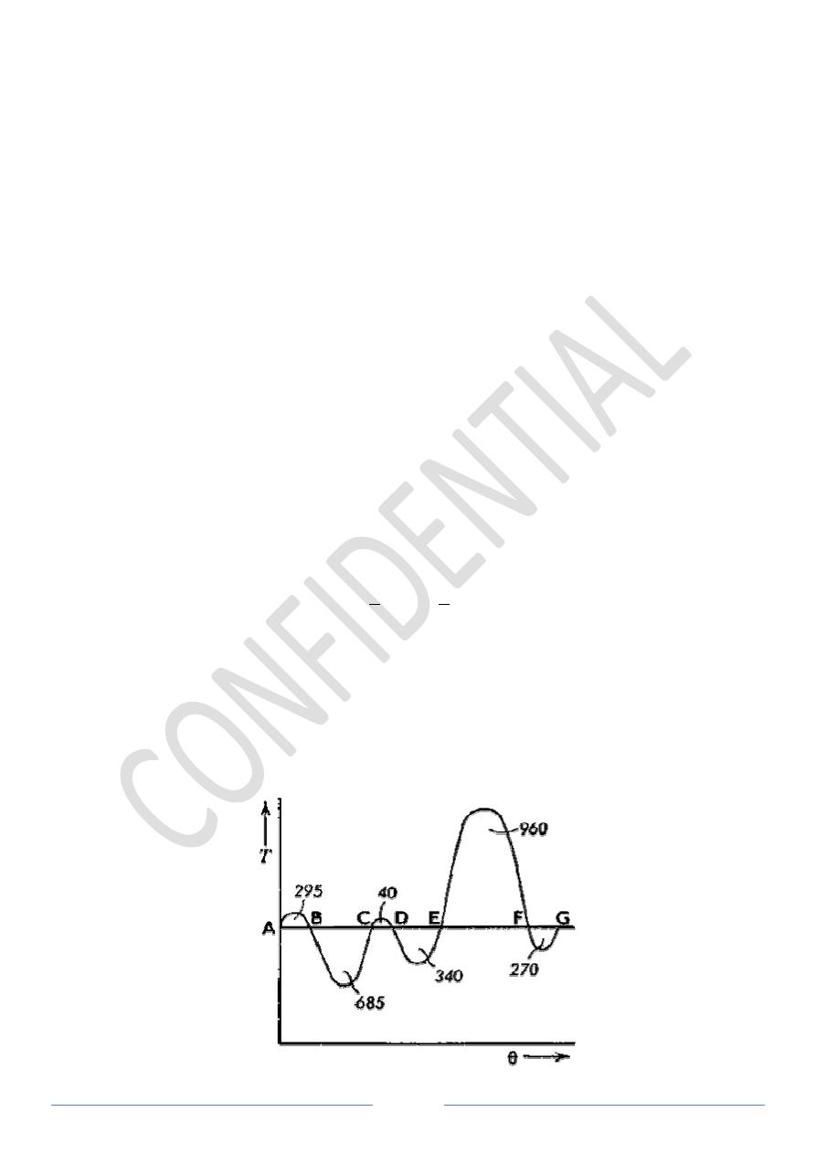
The turning moment diagram for a petrol engine is drawing to the following
5 N m; crank angle 1 mm = 1°. The turning moment
revolution of the engine and the areas above and below
turning moment line, taking in order, are 295, 685, 340, 960,
rotating parts are equivalent to a mass of 36 kg at a radius of gyration of
fluctuation of speed when the engine runs at 1800
Figure
m and mass 2500
Nm and may be assumed constant.
and (b) the kinetic energy of the
seconds from the
= 45
The turning moment diagram for a petrol engine is drawing to the following
. The turning moment
revolution of the engine and the areas above and below
, 270 mm
2
. The
kg at a radius of gyration of 150 mm.
1800 rev/min.
Figure 3
Solution:
I = m * k
2
= 36 * 0.15
2
ω = 2π*1800/60 = 188.5
Since the turning moment scale is 1
π/180 rad, therefore
1 mm
2
= on turning moment diagram =
Let the total energy at A = U, then referring to Figure
Energy at B = U + 295
Energy at C = U + 295 – 685 = U –
Energy at D = U + 295 – 685 + 40 = U
Energy at E = U + 295 – 685 + 40–
Energy at F = U + 295 – 685 + 40–
Energy at G = U + 295 – 685 + 40–
From above, the total energy is greatest at point B and least at point E.
Maximum fluctuation of energy
= . − . =
Coefficient of fluctuation of speed,
= ∗
∴
=
=
86
0.81 ∗ 188.5
= 0.00299
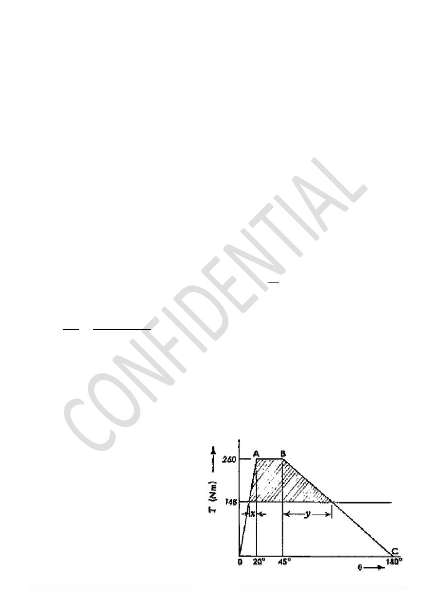
Example 4: The variation of crankshaft torque of a
approximately represented by taking the torque as zero for crank angles
260 N m for crank angles 20° and 45°
straight lines. The average speed is
machine requiring a constant torque, find the mass of the flywheel, of radius of gyration
250 mm, which must be fitted in order that the total variation of speed shall be
Solution:
The crankshaft torque diagram is shown
in Figure 4.
Page 5
2
= 0.81 kg m
2
188.5 rad/s
1 mm = 5 N m and crank angle scale is
= on turning moment diagram = 5 * π/180 = π/36 Nm
Let the total energy at A = U, then referring to Figure 3,
390
= U – 350
340 = U – 690
340 + 960 =U +270
340 + 960– 270 = Energy at A
the total energy is greatest at point B and least at point E.
= 985
= 985 ∗
36 = 86
00299 = 0.299%
The variation of crankshaft torque of a 4-cylinder petrol engine may be
approximately represented by taking the torque as zero for crank angles 0° and
45°, the intermediate portions of the torque graph being
aight lines. The average speed is 600 rev/min. Supposing that the engine drives a
machine requiring a constant torque, find the mass of the flywheel, of radius of gyration
mm, which must be fitted in order that the total variation of speed shall be
The crankshaft torque diagram is shown
Figure 4
N m and crank angle scale is 1 mm = 1° =
cylinder petrol engine may be
and 180° and as
the intermediate portions of the torque graph being
rev/min. Supposing that the engine drives a
machine requiring a constant torque, find the mass of the flywheel, of radius of gyration
mm, which must be fitted in order that the total variation of speed shall be 1 per cent.
Work done in 1/2 revolution = area OABC
=
1
2 ∗ 260 ∗ 20 ∗
180 +
∴ T
mean
= Work done /
θ = 465
From triangle ABC,
260 − 148
=
260
20 → ∴ = 8
And
260 − 148
=
260
135 → ∴ = 58
∴ x + y = 66.76
°
∴ Fluctuation of energy represented by shaded area
= 112 ∗ 25 ∗
180 +
112
2 ∗ 66
=
1
2 ∗
(
−
) = ∗
∗
∴ m = 46.2 kg
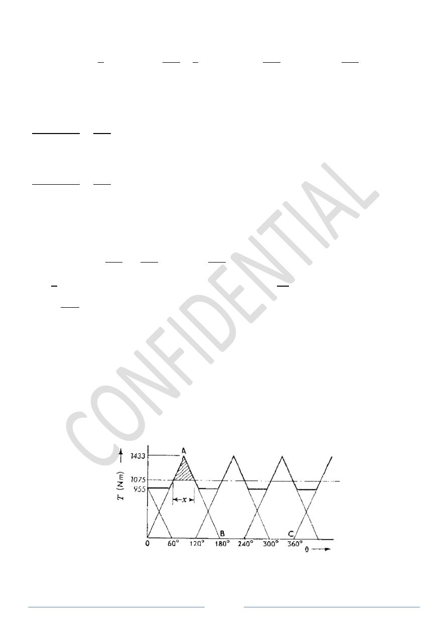
Example 5: An engine working on the two
120°. The turning moment for any cylinder is assumed to increase uniformly from zero to
a maximum while the crank turns 90°
remain zero over the remainder of the revolution
If the engine develops 15 kW per cylinder when running at a mean speed of
the turning moment diagram for one cylinder and from it construct the combi
Determine the variation in the kinetic energy of the flywheel and its required mass for a
radius of gyration of 0.3 m to limit the total speed variation to
Page 6
revolution = area OABC
+
1
2 ∗ 260 ∗ 135 ∗
180 + 260 ∗ 25 ∗
180
465 / π = 148 N m
8.61
°
58.15
°
represented by shaded area
66.76 ∗
180 = 114
∗
= ∗ 0.25
∗ (
2
60 ∗ 600)
∗ 0.01
An engine working on the two-stroke cycle has three cylinders with cranks at
. The turning moment for any cylinder is assumed to increase uniformly from zero to
90°, to fall uniformly to zero over the next
of the revolution.
kW per cylinder when running at a mean speed of
the turning moment diagram for one cylinder and from it construct the combi
Determine the variation in the kinetic energy of the flywheel and its required mass for a
m to limit the total speed variation to 2 rpm.
Figure 5
180 = 465
01
stroke cycle has three cylinders with cranks at
. The turning moment for any cylinder is assumed to increase uniformly from zero to
uniformly to zero over the next 90° and to
kW per cylinder when running at a mean speed of 400 rpm, draw
the turning moment diagram for one cylinder and from it construct the combined diagram.
Determine the variation in the kinetic energy of the flywheel and its required mass for a

Page 7
Solution:
OABC is the diagram for one cylinder, Figure 5.
∴ Work done per cycle per cylinder = Power * 60/ N = (15000 * 60) / 400 = 2250 J
∴ 2250 =
∗ =
1
2 ∗
∗
∴
= 1433
ℎ =
3 ∗ 2250
2
= 1075
From Figure 5,
∴ =
1433 − 1075
1433
∗ =
4
∴ , =
(1433 − 1075)
2
∗
4 = 140.6
∴ 140.6 =
1
2 ∗ ∗
(
−
) = ∗ ∗ (
−
) = ∗ 0.3
∗
2
60 ∗ 400
2
60 ∗ 2
∴ = 178
Example 6: A single cylinder internal-combustion engine working on the 4-stroke cycle
develops 75 kW at 360 rpm. The fluctuation of energy can be assumed to be 0.9 times the
energy developed per cycle. If the coefficient of fluctuation of speed is not to exceed 1 per
cent and the maximum centrifugal stress in the flywheel is to be 5.5 MN/m
2
, estimate the
mean diameter and the cross-sectional area of the rim. Cast-iron has a density of 7.2
Mg/m
3
.
Solution:
=
2 ∗ 360
60
= 12 /
=
75000 ∗ 60
180
= 25000
∴ = 0.9 ∗ 25000 = 22500
∴ 22500 =
1
2 ∗ ∗
(
−
) = ∗
∗
−
= ∗ (12 )
∗ 0.01
∴ = 1584
Centrifugal stress,
σ = ρ * v
2
=
ρ * ω
2
* R
2
where R is the mean rim radius,
i.e. 5.5* 10
6
= 7200 * 144π
2
* R
2
∴ R = 0.732 m, i.e. mean diameter, D = 2R = 1.464 m
I = mk
2
=
ρ * A * 2πR * R
2
where A is the cross-sectional area of the rim,
i.e.
1584 = 7200 * A * 2π * 0.732
∴ A = 0.0892 m
2
Example 7: A machine shaft running at a mean speed of
varies uniformly from 1200 Nm to
constant for the next one revolution, decreases uniformly to
revolution and then remains constant for the next
of operations. It is driven by a constant speed motor and a flywheel of radius of gyration
0.6 m is fitted to the shaft. If the fluctuation of speed is
1. The power of the motor, and
2. The mass of the flywheel required.
Solution:
Since the fluctuation of speed is
±2%
speed, therefore total fluctuation of speed,
−
= 4% = 0.04
and coefficient of fluctuation of speed,
=
−
= 0.04
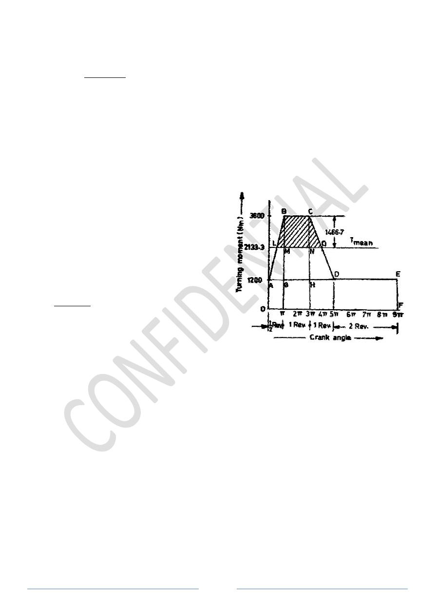
The turning moment diagram for the complete
cycle is shown in Figure 6.
ω = 2π*200/60 = 20.95 rad/s
We know that the torque required for one complete cycle
= Area OAEF + Area ABG + Area BCHG + Area DCH
= 9π * 1200 + 2400π/2
= 19200π Nm
∴ Mean torque, T
mean
= 19200π / 9π =
1. Power of the motor,
Power = 2π*N*T
mean
/60 = 2π *
2. Mass of the flywheel required
Let m = mass of the flywheel required,
First of all, let us find the values of LM
From similar triangles ABG and BLM
/ = / → ∴ =
Page 8
sectional area of the rim,
0.732
2
A machine shaft running at a mean speed of 200 rpm requires a torque which
Nm to 3600 Nm during the first half revolution, remains
constant for the next one revolution, decreases uniformly to 1200 Nm during the next one
on and then remains constant for the next two revolutions, thus completing a cycle
of operations. It is driven by a constant speed motor and a flywheel of radius of gyration
m is fitted to the shaft. If the fluctuation of speed is
±2% of mean speed, fi
The power of the motor, and
The mass of the flywheel required.
2% of mean
speed, therefore total fluctuation of speed,
and coefficient of fluctuation of speed,
The turning moment diagram for the complete
We know that the torque required for one complete cycle = Area of OALBCDEF
= Area OAEF + Area ABG + Area BCHG + Area DCH
2 + 2π * 2400 + 2π * 2400/2
π = 2133.3 Nm
π * 200 * 2133.3 / 60 = 44685 W = 44.685
Mass of the flywheel required
= mass of the flywheel required,
LM and NQ
BLM,
= 0.61
Figure 6
rpm requires a torque which
Nm during the first half revolution, remains
Nm during the next one
two revolutions, thus completing a cycle
of operations. It is driven by a constant speed motor and a flywheel of radius of gyration
of mean speed, find
= Area of OALBCDEF
44.685 kW
6

Page 9
Now from similar triangles CHD and CNQ,
/ = / → ∴ = 1.22
Since the fluctuation of energy is equal to the area above the mean torque line, therefore,
e = Area LBCQ = Area LBM + Area MBCN + Area NCQ
= 0.61π * 1466.7/2 + 2π *1466.7 + 1.22π * 1466.7/2 = 13435 Nm
And e = I * ω
2
* C
S
= mk
2
* ω
2
* C
S
∴ m = 13534 / (0.6
2
* 20.95
2
* 0.04) = 2126 kg
14.5 Dimensions of the Flywheel Rim:
Consider a rim of the flywheel shown in Figure 7;
Let
D = Mean diameter of rim = 2R
R = Mean radius of rim
A = Cross-sectional area of rim
ρ = Density of rim
ω = Angular velocity of the flywheel
σ = Centrifugal or hoop stress
v = Linear velocity of the mean radius = ω * R
b = Width of rim
t = thickness of rim
D
t
b
σ = ρ * v
2
=
ρ * ω
2
* R
2
=
=
∗ ∗
60
= ∗
m
rim
= Volume * density = 2π * R * A *
ρ
Figure 7
Page 10
A = m
rim
/ (2π * R *
ρ) = b * t
Example 8: The turning moment diagram for a multi-cylinder engine has been drawn to a
scale of 1 cm of 5000 Nm torque and 1 cm to 60° of crank displacement. The intercepted
areas between output torque curve and mean resistance line taken in order from one end in
square cm are:
-0.3, +4.1, -2.8, +3.2, -3.3, +2.5, -3.6, +2.8, -2.6 cm
2
, when the engine is running at 800
rpm.
The fluctuation of speed is not to exceed 2% of the mean speed. Determine a suitable
mean diameter and cross-section of the flywheel rim for a limiting value of the safe
centrifugal stress of 7 MN/m
2
. The material density may be assumed as 7.2 Mg/m
3
. The
width of the rim is to be 5 times the thickness.
Solution:
C
S
= 2% = 0.02
ω = 2π*800/60 = 83.8 rad/s
From the figure above we find that the maximum energy is at point E = U + 4.2 and the
minimum is at point H = U – 0.2
∴ e = U + 4.2 – U + 0.2 = 4.4 cm
2
1 cm
2
= 5000 * 60π/180 = 5235.987
≅ 5236 N m
∴ e = 5236 * 4.4 = 23038.4 N m
Also e = 2E * C
S
∴ E =23038.4 / 0.04 = 575960 N m
σ = ρ * v
2
→
v = (7*10
6
/7200)
0.5
= 31.18 m/s
and v = π*D*N/60
→
D = 0.74438 m
=
1
2
∗
∴ m
rim
= 2E / v
2
= 1184.868 kg
-0.3
+3.2
-2.6
Crank angle
T
u
rn
in
g
m
o
m
ent

Page 11
A = m
rim
/ (π * D *
ρ) = 0.07037 m
2
A = b * t, b = 5t,
∴ A = 5t
2
,
∴ t = 0.1186 m ≅ 119 mm
∴ b = 5 * 119 = 595 mm

Page 12
Problems (Flywheel):
Q1/ A double-acting steam engine runs at 100 rev/min. A curve of the turning-moment
plotted on a crank angle base showed the following areas alternately above and below the
mean turning-moment line: 780, 400, 520, 620, 260, 460, 340, and 420 mm
2
. The scales
used were 1 mm = 400 N m and 1 mm = 1° crank angle.
If the total fluctuation in speed is limited to 1.5 per cent of the mean speed, determine the
mass of the flywheel necessary if the radius of gyration is 1.05 m.
(Ans.: 3464 kg)
Q2/ The turning-moment diagram for an engine is drawn on a base of crank angle and the
mean resisting torque line added. The areas above and below the mean line are +4400, -
1150, +1300, -4550 mm
2
, the scale being 1 mm = 100 N m torque and 1 mm = 1° of crank
angle.
Find the mass of flywheel required to keep the speed between 297 and 303 rpm, if its
radius of gyration is 0.525 m.
(Ans.: 1460 kg)
Q3/ The turning-moment diagram for an engine, which has been drawn to scales of 1 mm
to 50 N m and 1 mm to 1° of rotation of crankshaft, shows that the greatest amount of
energy which has to be stored by the flywheel is represented by an area of 2250 mm
2
. The
flywheel is to run at a mean speed of 240 rpm with a total speed variation of 2 per cent. If
the mass of the flywheel is to be 450 kg, determine suitable dimensions for the rim, Cast
iron has a density of 7.2 Mg/m
3
.
(Ans.: 1.237 m external diameter, 274 mm width)
Q4/ A vertical diesel engine running at 350 rpm develops 600 kW and has 4 impulses per
revolution. If the fluctuation of energy is 25 per cent of the work done during each
impulse, estimate the cross-sectional area of the rim of the flywheel required to keep the
speed within 2 rpm of the mean speed when the mean peripheral speed of the rim is 1350
m/min. Cast iron has a density of 7.2 Mg/m
3
.
(Ans.: 0.04 m
2
)
Q5/ A machine press is worked by an electric motor, delivering 2.25 kW continuously. At
the commencement of an operation, a flywheel of moment of inertia 50 kg m
2
on the
machine is rotating at 250 rpm. The pressing operation requires 4.75 kJ of energy and
occupies 0.75 second. Find the maximum number of pressing that can be made in 1 hour
and the reduction in speed of the flywheel after each pressing. Neglect friction losses.
(Ans.: 1705, 23.5 rev/min)
Q6/ An engine has 3 single acting cylinders, the cranks being spaced 120° apart. For each
cylinder, the crank effort diagram consists of a triangle:
Angle
0°
60°
180°
180° to 360°
Torque (N m)
0
200 (max.)
0 0
Find the mean torque and the moment of inertia of the flywheel in kg m
2
necessary to keep
the speed within 180
± 3 rpm.
(Ans.: 150 N m; 2.21 kg m
2
)
Q7/ A shaft fitted with a flywheel rotates at 250 rpm and drives a machine the resisting
torque of which varies in a cyclic manner over a period of three revolutions. The torque
rises from 675 Nm to 2700 Nm in a uniform manner during 0.5 revolution and remains
constant for 1 revolution, the cycle being then repeated.

Page 13
If the driving torque applied to the shaft is constant and the flywheel has a mass of 450 kg
and a radius of gyration of 0.6 m, find the power necessary to drive the machine and the
percentage fluctuation of speed.
(Ans.: 44.2 kW,
± 3.58 per cent)
Q8/ A single cylinder four stroke internal combustion engine develops 30 kW at 300
rev/min. The turning-moment diagram for the expansion and compression strokes may be
taken as two isosceles triangles, on bases 0 to π and 3π to 4π radians respectively, and the
net work done during the exhaust and inlet strokes is zero. The work done during
compression is negative and is one quarter of that during expansion.
Sketch the turning moment diagram for one cycle and find the maximum value of the
turning moment during expansion.
If the load remains constant, mark on the diagram the points of maximum and minimum
speed. Also find the moment of inertia, in kg m
2
, of a flywheel to keep the speed
fluctuation within
±1.5 per cent of the mean speed. (Ans.: 10.186 kN m, 457.8 kg m
2
)
Q9/ Figure 8 shows the variation with time of the torque required on the driving shaft of a
machine during one cycle of operations. The shaft is direct coupled to an electric motor
which exerts a constant torque and runs at a mean speed of 1500 rpm. The rotating parts
are equivalent to a flywheel of mass 18 kg with a radius of gyration of 250 mm.
Determine (a) the power of the motor, neglecting friction; (b) the percentage fluctuation of
speed.
(Ans.: 2.075 kW; 6.275 per cent)