Dr. Sameir Abd Alkhalik Aziez
University of Technology Lecture (3))
-
١٢
-
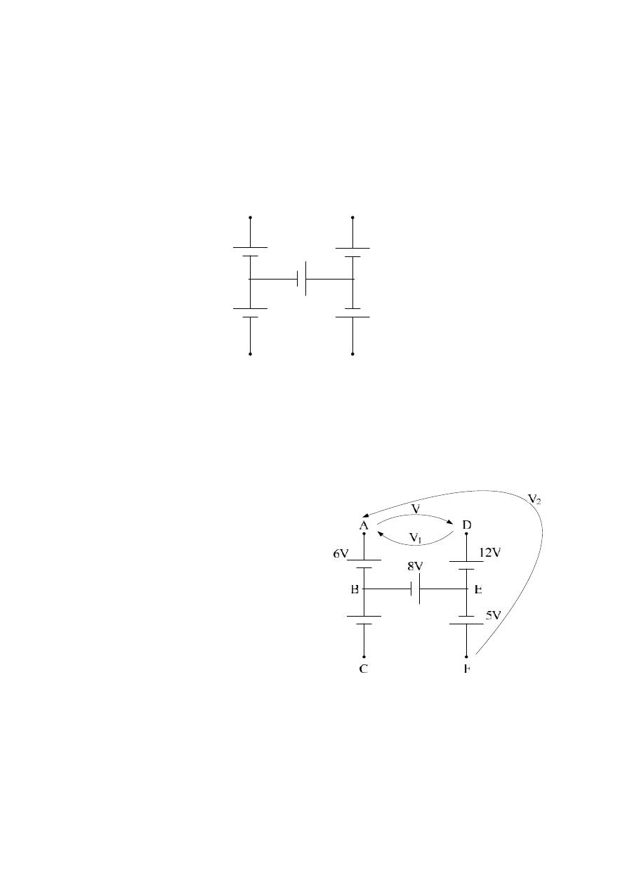
Example :- For the following circuit diagram , find the potential difference
between Node ( A & D ) , and Node ( A & F ) ?
5V
12V
8V
6V
C
F
D
A
B
E
Solution : To find the potential difference between Node A & D , we will apply
K.V.L. on the closed loop BADEB
Take the loop FEDAF to find the potential difference between Node C & F .
–5 + 12 – V – V
2
= 0
–5 + 12 – 14 – V
2
= 0
–7–V
2
= 0
V
2
=
–7 volt .
Or Take the loop FEBAF
–5 –8 +6 – V
2
= 0
V
2
=
–7 volt .
+6 + V
– 12 – 8 = 0
V = 20
– 6 = 14 volt
or
+6
– V
1
– 12 – 8 = 0
–14 – V
1
= 0
V
1
=
–14 volt
*
ﺔـطﻘﻧ دﻬﺟ نا كﻟذ ﻰﻧﻌﻣ
D
دـﻬﺟ نـﻣ ﻰـﻠﻋأ
ﻧﻘطﺔ
A
ـﺑ
٤١
ﻓوﻟت
.
Dr. Sameir Abd Alkhalik Aziez
University of Technology Lecture (3))
-
٢٢
-
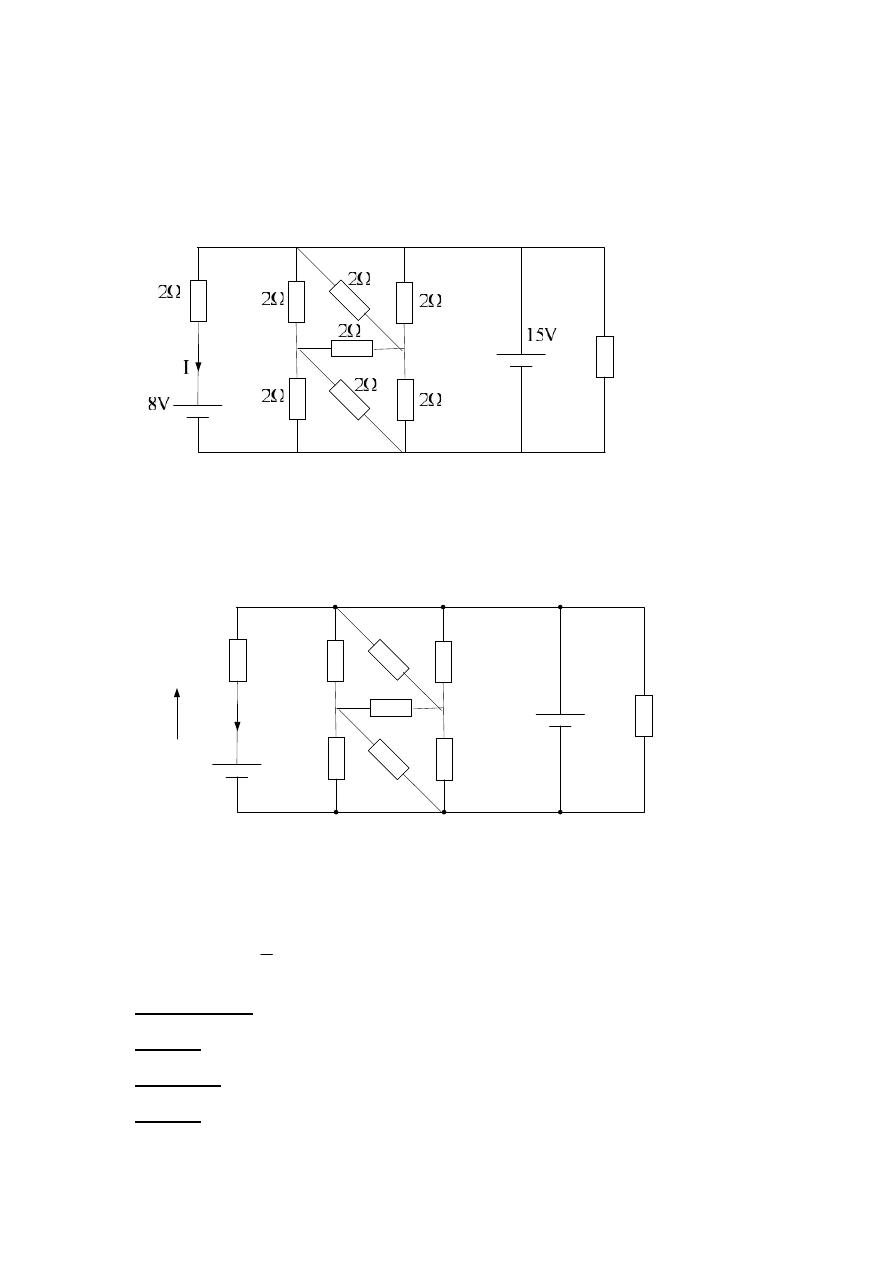
Example :- For the following circuit diagram , find the current ?
Solution :
3Ω
15V
8V
2Ω
2Ω
2Ω
2Ω
2Ω
2Ω
2Ω
2Ω
I
V
A
B
C
F
E
D
Take the loop FABCDEF
+8 + V
– 15 = 0
+V
– 7 = 0
V = +7 volt
V = IR
A
I
5
.
3
2
7
Definitions :-
Node :- Meeting point of 3 or more branches .
Branch :- Series of elements carrying the same current .
Loop :- Is any closed path in a circuit .
Dr. Sameir Abd Alkhalik Aziez
University of Technology Lecture (3))
-
٣٢
-
Hence for the loop circuit, we can find :-
E
1
E
2
V
3
V
4
A
B
D
C
E
3
V
1
V
2
Take the loop ABCDA ; to find V
3
–E
2
+ E
3
+ V
3
+ E
1
= 0
V
3
= E
2
– E
3
– E
1
V
4
=
–V
3
Or;
–E
2
+ E
3
– V
4
+ E
1
= 0
V
4
= E
1
+ E
3
– E
2
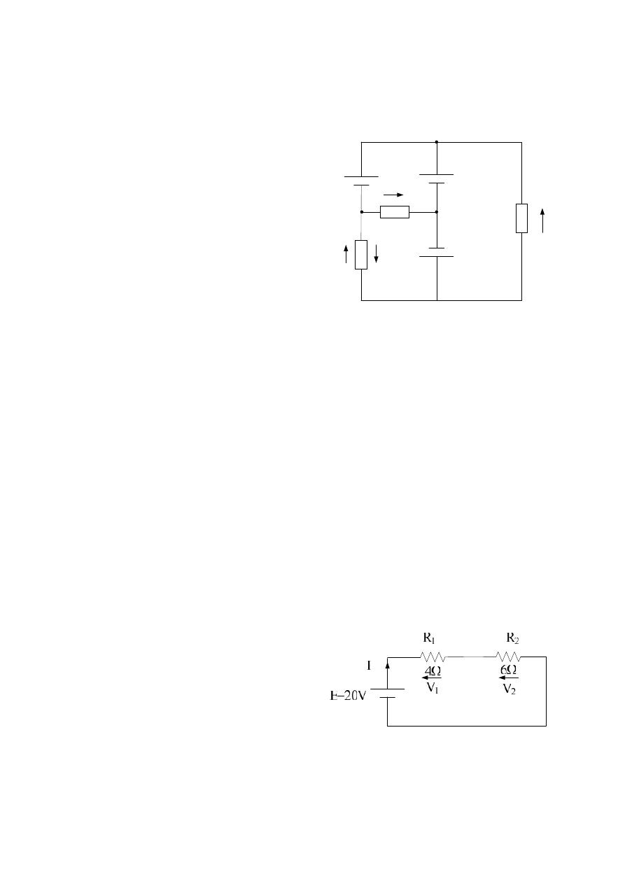
Example :- For the following circuit diagram , find ; R
T
, I , V
1
, V
2
, P
4
Ω
, P
6Ω
, P
E
, verify by K.V.L. ?
Solution :-
R
T
= R
1
+ R
2
= 4 + 6 = 10
4 nodes and 6 branches
and we can find : V
1
, V
2
, V
3
and V
4
as follows :-
Take the loop BACB ; to find V
1
E
2
– V1 – E
3
= 0
V
1
= E
2
– E
3
Or, if we take BCAB ;
E
3
– V1 – E
2
= 0
V
1
= E
2
– E
3
Take the loop ADBA ; to find V
2
–E
1
+ V
2
+ E
2
= 0
V
2
= E
1
– E
2

Dr. Sameir Abd Alkhalik Aziez
University of Technology Lecture (3))
-
٤٢
-
A
R
E
I
T
2
10
20
V
IR
V
8
4
2
1
1
V
IR
V
12
6
2
2
2
W
R
I
P
16
4
2
2
1
2
4
; or
w
R
V
P
16
4
8
2
1
2
1
4
W
R
I
P
24
6
2
2
2
2
6
; or
w
R
V
P
24
6
12
2
2
2
2
6
W
IE
P
E
40
20
2
; or
W
P
P
P
E
40
24
16
6
4
To verify results by using K.V.L. ; then
0
1
N
i
i
V
E
– V
1
– V
2
= 0
E = V
1
+ V
2
20 = 8 + 12
20 = 20 checks
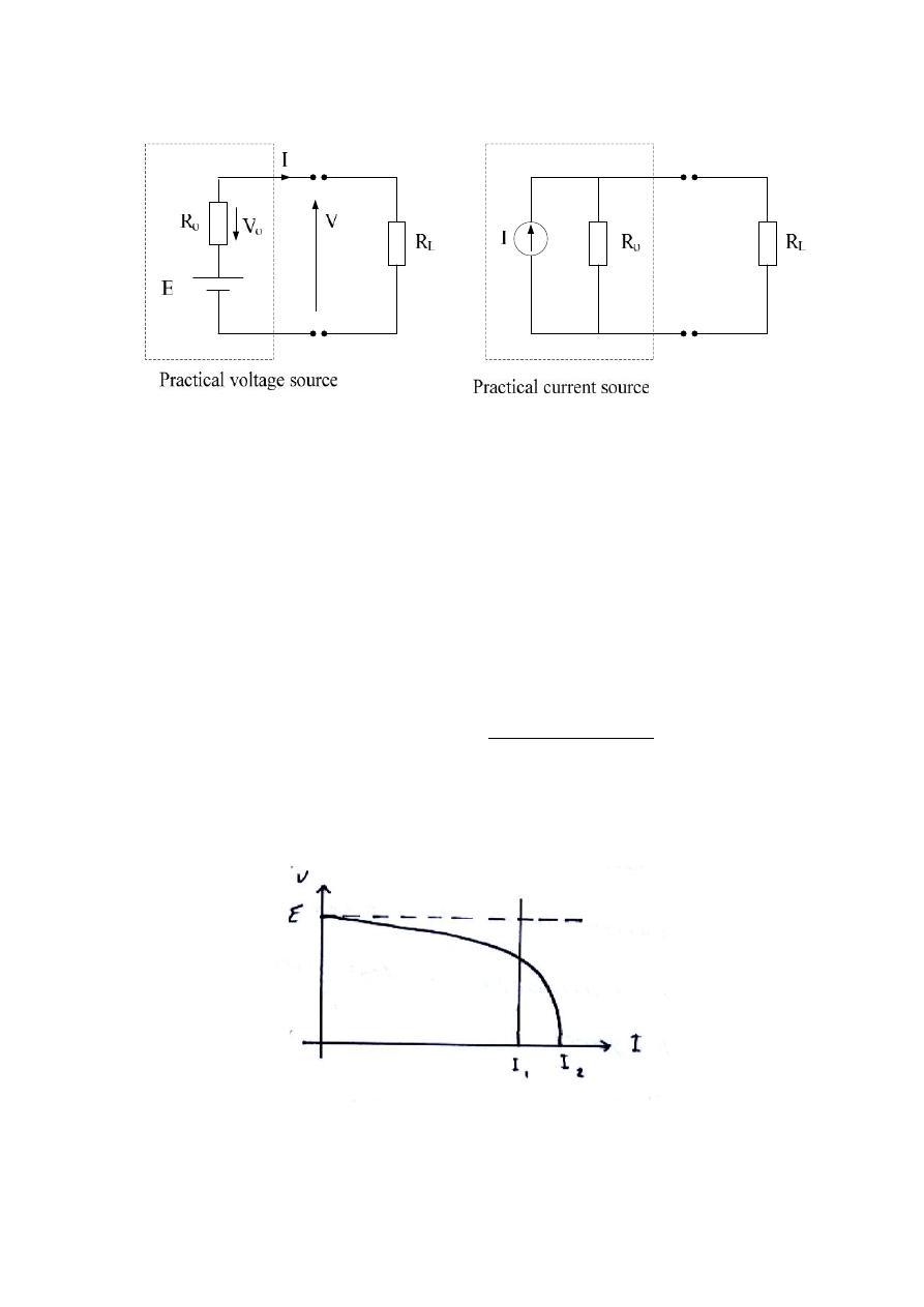
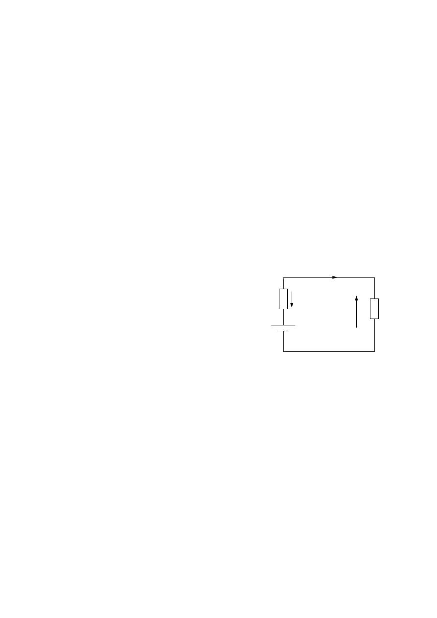
Internal Resistance :-
Every practical voltage or current source has an internal resistance that
adversely affects the operation of the source.
In a practical voltage source the internal resistance represent as a resistor in series
with an ideal voltage source.
In a practical current source the internal resistance represent as a resistor in
parallel with an ideal current source, as shown in the following figures.
Dr. Sameir Abd Alkhalik Aziez
University of Technology Lecture (3))
-
٥٢
-
Where
R
o
= Internal resistance
R
L
= load resistance
According to K.V.L.
E
– V
o
– V = 0
E
– IR
o
– V = 0
V = E
– IR
o
Note that an ideal sources have R
o
= 0
We can representing a load as a group of parallel resistances.
Hence as the load will increase the current will be increase ( because the
resistance will decrease ) and the voltage will decrease .
This is because the drop voltage due to the internal resistance , as shown in the
following figure :-
Dr. Sameir Abd Alkhalik Aziez
University of Technology Lecture (3))
-
٦٢
-
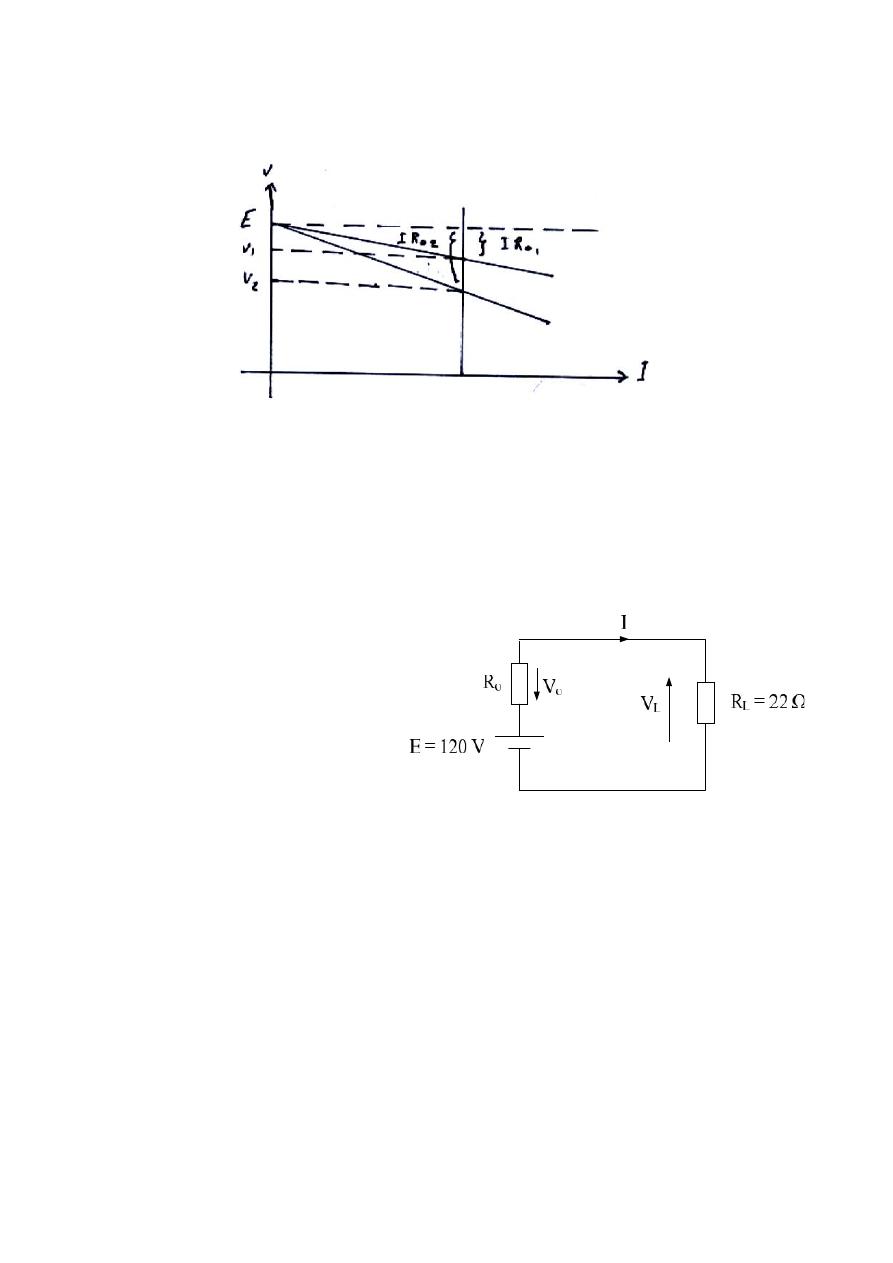
As seen
from the above
figure , if R
o2
> R
o1
, then V
2
< V
1
and the drop voltage will be ( E
– V
2
) ,
which is greater than ( E
–V
1
) .
Example :- For the following circuit diagram , calculate I and V
L
for the
following cases :-
Solution :-
a.) By apply K.V.L.
E
– V
o
– V = 0
120
– IR
o
– IR
L
= 0
120
– 0 – 22I = 0
120 = 22I
I = 5.46 A
V
L
= I R
L
= 5.46 * 22 = 120 V
b.) E
– V
o
– V = 0
120
– 8I – 22I = 0
120
– 30I = 0
a)
Ro = 0 Ω
b)
Ro = 8 Ω
c)
Ro = 16 Ω
Dr. Sameir Abd Alkhalik Aziez
University of Technology Lecture (3))
-
٧٢
-
120 = 30I
I = 4 A
V
L
= I R
L
= 4 * 22 = 88 V
c.) E
– V
o
– V = 0
120
– 16I – 22I = 0
120
– 38I = 0
120 = 38I
I = 3.16 A
V
L
= I R
L
= 3.16 * 22 = 69.5 V
Then we can conclude that as R
o
increase the total current and load voltage will
decrease.
Example :- A circuit have load one with 20
Ω and 4A , and load two with 10 Ω
& 6A . Find the current for load three which have 30
Ω ?
E
I
V
o
R
o
R
L
V
L
V
L
= E
– IR
o
IR
L
= E
– IR
o
4 * 20 = E
– 4R
o
80 = E
– 4R
o
Also
6 * 10 = E
– 6 R
o
60 = E
– 6R
o
Solution :-
1)
20 Ω & 4A
2)
10 Ω & 6A
3)
30 Ω & I = ?
From K.V.L. , then
E
– V
o
– V
L
= 0
-----------------
( 1 )
-----------------
( 2 )
Dr. Sameir Abd Alkhalik Aziez
University of Technology Lecture (3))
-
٨٢
-
From eq. (1) & (2) , we have
20 = ( 6
– 4 ) R
o
R
o
= 10 Ω ; sub. this result it in eq. (1) , then
80 = E
– 4 * 10
E = 120 V
Now , we Apply K.V.L. for load 3 ;
V
3
= E
– IR
o
30I = 120
– 10I
40I = 120
I = 3 A for load three.
See from this example that the current will increase as the load will decrease
with constant E & R
o
.
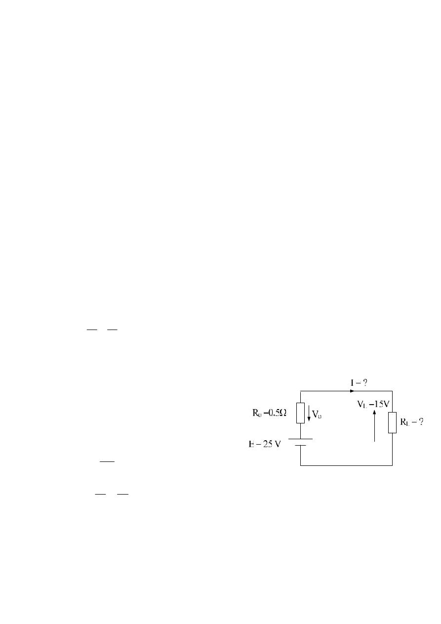
Example :- A circuit have V
oc
= 25 v and I
sc
= 50 A , find its current and R
L
when V
L
= 15 V ?
Solution :-
E = Voc = 25 V
5
.
0
50
25
sc
o
I
E
R
From K.V.L.
E
– V
o
– V
L
= 0
E
– 0.5I – 15 = 0
25
– 0.5I – 15 = 0
0.5I = 25
– 15
A
I
20
5
.
0
10
75
.
0
20
15
I
V
R
L
L